As we covered in Part 1, there are many auxiliary ops needed to stabilize the numerics of NVFP4 training.
Now we shift our focus to systems engineering: achieving stability without giving up performance.
Specifically, we will dissect TransformerEngine's implementation of the NVFP4 recipe:
- We'll start by examining
TE'sNVFP4recipe and the underlying modules and data structures for managingNVFP4tensors. - Next, we'll trace the computation flow of an
NVFP4linear layer, unpacking how data flows through the 3 GEMMs –FProp,DGrad, andWGrad– and the custom kernels that augment this flow. - Finally, we'll dive deep into one such kernel, providing a detailed walkthrough of an
sm100a-specialized kernel that also serves as a capstone of the stabilization and performance topics we've covered in these posts.
NVFP4 Recipe
TransformerEngine exposes a high-level API for NVFP4 training.
import torch
import transformer_engine.pytorch as te
from transformer_engine.common.recipe import NVFP4BlockScaling

recipe = NVFP4BlockScaling()
high_precision_dtype = torch.bfloat16

# TE's custom linear layer
linear = te.Linear(768, 2048, params_dtype=high_precision_dtype, bias=False, device="cuda")

x = torch.rand((1024, 768), dtype=high_precision_dtype, requires_grad=True, device="cuda")

# Mixed precision context
with te.autocast(enabled=True, recipe=recipe):
    out = linear(inp)

loss = out.mean()

# Backward is automatically handled by te.Linear's custom autograd
loss.backward()
The default recipe is as we described in Part 1:
class NVFP4Recipe:

  """
  `x`
  - FProp: 1D rowwise RTNE quantization
  - WGrad: rht + 1D colwise RTNE quantization
  """
  self.fp4_quant_fwd_inp = QParams(
      random_hadamard_transform=not self.disable_rht, # disable_rht = False unless explicitly disabled, only active for backwards
      stochastic_rounding=False,
      fp4_2d_quantization=False,
  )

  """
  `W`
  - FProp: 2D rowwise RTNE quantization
  - DGrad: 2D colwise RTNE quantization
  """
  self.fp4_quant_fwd_weight = QParams(
      random_hadamard_transform=False,
      stochastic_rounding=False,
      fp4_2d_quantization=not self.disable_2d_quantization, # 2D quantization is on by default
  )

  """
  `dy`
  - DGrad: 1D SR rowwise quantization
  - WGrad: rht + 1D SR colwise quantization
  """
  self.fp4_quant_bwd_grad = QParams(
      random_hadamard_transform=not self.disable_rht, # on by default for WGrad
      stochastic_rounding=not self.disable_stochastic_rounding, # on by default for both WGrad and DGrad
      fp4_2d_quantization=False,
  )
NVFP4 Modules and Tensor Management
The key TE classes that instrument this flow are TE.Linear, NVFP4Quantizer, and NVFP4Tensor/Storage.
TE.Linear / TE._Linear
TE._Linear is the custom autograd function that conducts the forward and backwards functions for all TE mixed precision types; TE.Linear is the wrapper class that sets up quantizers, distributed knobs, and other configs.
When run within an NVFP4Recipe context, TE.Linear dispatches to NVFP4Quantizer for quantization and NVFP4Tensor/NVFP4TensorStorage for storing quantized data and metadata.
TransformerEngine has both a module and a newer functional Linear backend.
We'll focus on the former since it is the older, more stable API, though the newer functional version does have additional affordances such as custom fusible ops.
NVFP4Quantizer
NVFP4Quantizer is the python interface to the custom CUDA kernels that perform the actual quantization ops.
NVFP4Tensor / Storage
NVFP4Tensor and NVFP4TensorStorage are tensor-like classes for representing and managing NVFP4 buffers and metadata.
class NVFP4Tensor(NVFP4TensorStorage, QuantizedTensor):
    """Quantized tensor class with FP4 data

    The tensor presents as having a standard, higher-precision dtype,
    but the data itself is (scaled) FP4. For most tensor operations,
    the data will be cast to the nominal dtype before performing the
    operation.

    Parameters
    ----------
    rowwise_data : torch.Tensor
        Raw FP4 data in a uint8 tensor (rowwise layout).
    rowwise_scale_inv : torch.Tensor
        Reciprocal of the scaling factor applied when
        casting to FP4, i.e. the scaling factor that must
        be applied when casting from FP4 to higher
        precision (rowwise).
    columnwise_data : torch.Tensor, optional
        Raw FP4 data in a uint8 tensor (columnwise layout).
    columnwise_scale_inv : torch.Tensor, optional
        Reciprocal of the scaling factor for columnwise FP4 data.
    amax_rowwise : torch.Tensor, optional
        Rowwise amax tracking tensor.
    amax_columnwise : torch.Tensor, optional
        Columnwise amax tracking tensor.
    fp4_dtype : TE_DType
        The FP4 data type used for quantization.
    quantizer : Quantizer
        The quantizer instance used for this tensor.
    dtype : torch.dtype, default = torch.float32
        Nominal tensor datatype, used in dequantize.
    """


class NVFP4TensorStorage(QuantizedTensorStorage):
    """Mixin class that holds data attributes of NVFP4Tensor.

    NVFP4Tensor inherits from the PyTorch tensor class and this mixin
    class. If this class is instantiated directly, it has the same
    data, lower CPU overhead, and less functionality. It should only
    be instantiated directly for performance-critical internal usage.

    """
  ...
NVFP4Tensor is a standalone pytorch tensor subclass and carries all the pytorch autograd and dispatch machinery.
NVFP4TensorStorage, on the other hand, is a low-overhead, internally-managed container for NVFP4 data and is decoupled from the pytorch computation graph.
- Since
NVFP4quantization / dequantization is encapsulated by theTE.Linearautograd function, the lifecycle ofNVFP4tensors can be managed entirely byTEitself. - Ops on this type hence don't need to be go through torch
autogrador any of the normal dispatch machinery of torch tensors, eliminating CPU overhead. - This also allows fine-grained management of
NVFP4buffers and metadata.
When using the high-level autocast API with TE.Linear layers, the entire quantization flow happens entirely within TE.Linear's scope, thus, the module defaults to NVFP4TensorStorage as the tensor type.
- Within the
NVFP4autocast scope,TE.Linear's quantizer type is set toNVFP4Quantizer - When the quantizers for each GEMM input type are created, an
internalflag is set - This flag determines the
NVFP4Tensortype to create during quantization, which occurs at the Cpp extension level.
The fields that are managed by NVFP4Tensor / Storage:
class NVFP4Tensor(...)
  ...
  _rowwise_data: Optional[torch.Tensor]
  _columnwise_data: Optional[torch.Tensor]
  _quantizer: Optional[Quantizer]
  _rowwise_scale_inv: torch.Tensor
  _columnwise_scale_inv: torch.Tensor
  _fp4_dtype: TE_DType
  _amax_rowwise: torch.Tensor
  _amax_columnwise: torch.Tensor
_rowwise_data/_columnwise_data: buffers for packed, quantizedFP4E2M1data_quantizer:NVFP4Quantizer(see above)_rowwise_scale_inv/_columnwise_scale_inv: buffers forFP8E4M3blockwise scale factors_amax_rowwise/_amax_columnwise: 2nd-levelFP32scale factors
Recall that due to tensor core constraints, blockscale quantization must be along the reduction dimension.
Assume the following dimensions for the original, high-precision inputs, all with row-major layouts per pytorch convention:
FProp
⟹ is quantized along rows, is also quantized along rows.
-
is set to use rowwise quantization here in
Linear.forwardand to rowwise as well here. The quantized shapes are thus:
The factor of comes from the fact that FP4E2M1 are 2x packed into an uint8_t.
DGrad
⟹ is quantized along rows, is quantized along columns.
WGrad
⟹ is quantized along columns, is quantized along columns.
-
is explicitly set to use columnwise quantization and similarly for here
Note that TransformerEngine stores columnwise data as transposed row-major.
Using to denote columnwise quantization:
Tensor management
Given the asymmetry of forward / backward quantization, TransformerEngine carefully manages computation to minimize round-trip movement for memory-bound quantization ops and discards tensors when possible to reduce memory footprint.
TEcomputes both rowwise and columnwise quantization in a single extension call (e.g., is quantized in both orientations during the forward pass) and also fuses kernels when possible to increase arithmetic intensity of memory-bound kernels, as we'll see below.- Discards tensors from the forward pass (e.g., , and ) which are not used in backward GEMMs.
- Interestingly, rowwise / is not discarded in the module linear implementation even though it is not needed in backwards (except when using gradient accumulation / microbatching); notably, the functional linear does discard the quantized rowwise weight data.
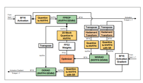
NVFP4 Computation Flow
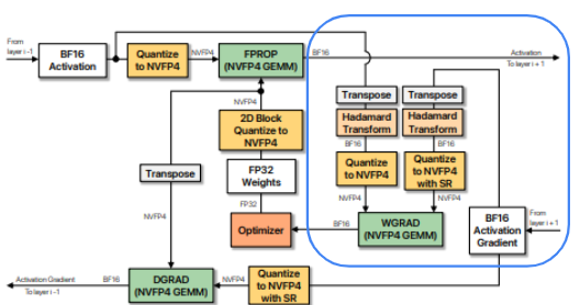
Before we dive into TransformerEngine's optimized kernels, let's review the 3 GEMMs in the NVFP4 linear layer.
FProp
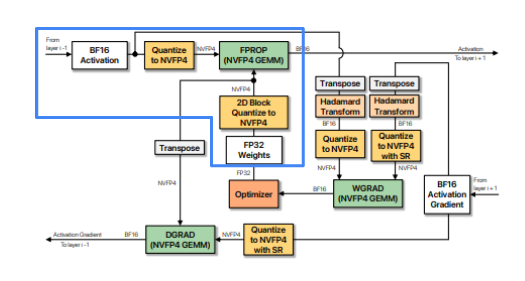
Inputs are and
- needs to be
RTNE-quantized with1Dblockscales along rows - is
2DrowwiseRTNE-quantized
The FProp computation flow:
- Compute global amax for →
FP32 - Rowwise quantize in
1 x 16blocks →E2M1+E4M3scale factors - Compute global amax for →
FP32 - Rowwise quantize in
16 x 16blocks →E2M1+E4M3scale factors - Swizzle scale factors to tensor core conformant layout; ditto for
- Call
cublasLtblockscaled GEMM with:E2M1+FP32+E4M3E2M1+FP32+E4M3
DGrad
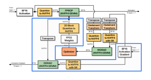
Inputs are and
- needs to be
SR-quantized with1Dblockscales along rows - For , we need , , , where the quantized values and scale factors are columnwise.
For DGrad, the computation flow is similar to FProp:
- Global amax of →
- is rowwise quantized with stochastic rounding and encoded blockwise scale factors computed → and
- Global amax of →
- is columnwise 2D block quantized → and
- and are swizzled to blockwise gemm scale format
- Blockscale gemm with:
E2M1+FP32+E4M3E2M1+FP32+E4M3
WGrad
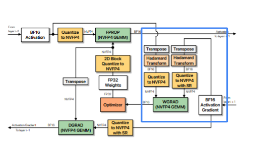
Inputs are and
- needs to be
RHTpre-conditioned thenRTNE-quantized with1Dblockscales along columns - also needs
RHTthenSR-quantized with1Dblockscales along columns.
The computation flow for WGrad:
- Apply
RHTto → - Compute global amax for →
FP32 - Quantize in
1 x 16blocks along rows (so columnwise quantization of ) →E2M1+E4M3scale factors - Apply
RHTto → - Compute global amax for →
FP32 - Quantize in
1 x 16blocks along rows (columnwise quantization of ) →E2M1+E4M3scale factors - Swizzle and
- Call
cublasLtblockscaled GEMM with:E2M1+FP32+ swizzledE4M3E2M1+FP32+E4M3swizzled
Custom Kernels
Now that we understand the computations needed for each GEMM, we'll trace how TransformerEngine implements this flow at a kernel level.
For each of the kernels, I'll provide a high-level description of the kernel structure (work partitioning, data movement, and compute patterns) and links to the relevant source code.
Then in the final section, I'll dissect a specific kernel that fuses many of the concepts we have covered throughout this blogpost.
FProp
1. Global amax for
TransformerEngine combines the computation of with the computation of through the fused kernel HadamardAmaxTmaKernel.
- Inputs: ; Outputs: and
- Each
CTA, 4 warps / 128 threads, processes a128 x 128tile, split into 464 x 64pipeline stages, double buffered in shared memory. - Each
64 x 64stage is computed in 4 iterations, each iteration covering a16 x 64stripe, with each warp processing a16 x 16block within the stripe.- The random hadamard matrix is constructed on device, where 8 values of the
16 x 16matrix are created (and reused) per thread, corresponding to the thread-value ownership ofwmma.m16n16k16.
- The random hadamard matrix is constructed on device, where 8 values of the
- Within the main compute kernel, a
16 x 16tile is loaded per warp, transposed andRHTapplied, then local per-threadamaxcomputed for the path and local per-threadamaxfor the path, reusing the already resident register values.- For the
rhtpath, each warp loads a16 x 16tile of the input tensor from shared memory, unswizzling the swizzling from theTMAload. - The tile is loaded from shared memory to registers using a warp-wide ldmatrix and transposed in place.
- The
rhtis applied to the local16 x 16tile by issuing a16 x 16 x 16wmma, then local post-rht amax reduced. - Next, the thread-local
amaxfor the pre-rht is calculated, using the already loaded values of the input tensor.
- For the
- After the entire
128 x 128tile has been processed, a final global amax is calculated for the pre and post-rhtlocal amaxes then stored as and .
- Each
2. Quantization of
quantize_transpose_nvfp4 converts inputs to FP4E2M1 and calculates FP8E4M3 scales factors for each 1 x 16 block.
- Inputs: , ; Outputs: ,
- 4 warps / 128 threads per
CTAprocesses a128 x 128tile of pipelined in 432 x 128slices- Each warp processes a
32 x 32block of the32 x 128slice, in 2 iterations, each thread responsible for 11 x 16block per iteration:- 2 threads per warp * 4 warps * 16 elements per thread = 128 columns
- (32 threads per warp // 2 threads per row) = 16 rows per iteration
16 x 128tile per iteration * 2 iterations =32 x 128tile
- Uses 2 shared memory buffers pipelined in 4 stages.
- Each warp processes a
TMAloads tiles of along with pre-computed from (1).- Computes blockwise scale factors following the NVFP4 Quantization Protocol and stores as fp8_e4m3.
- Calculates row-wise and stores as packed fp4x2_e2m1x2.
- 4 warps / 128 threads per
3. Global amax for
is computed using a standard reduction kernel.
4. Fused Weight Quantization
Both the rowwise and columnwise quantization of are fused in quantize_transpose_nvfp4_2D_kernel.
- Inputs: , ; Outputs: , , ,
- Similar overall structure as the activation quantization kernel: double-buffered
TMAkernel where each threadblock processes128 x 128tiles in 432 x 128slices. - Primary differences are the blockwise amax calculation and the fusion of both the rowwise and columnwise quantization within the same kernel.
- Blockwise amaxes are calculated in
16 x 16blocks using local → warp reductions then cached in shared memory for columnwise and rowwise quantization.- The
32 x 128slice is processed in 2 iterations:- 128 threads across 128 columns, each thread calculating the columnwise max.
- A half-warp reduction then reduces across 16 block rows.
- Lanes 0 and 16 write the resulting 8 blockwise amaxes to shared memory (per iteration).
- The
- Quantization: in contrast to the quantization of , both the rowwise and columnwise are computed (for , a separate kernel is needed for fusing
rhtwith columnwise quantization).- Columnwise
- Each thread is responsible for quantizing a column of the
32 x 128tile. - Threads load columns of data from
smemand use pre-computed block amaxes to calculate scale factors and quantized values .
- Each thread is responsible for quantizing a column of the
- Rowwise
- Similar to the earlier activation quantization kernel, the 128 threads are arranged
16 x 8, with each thread processing 8 columns such that the entire32 x 128tile is processed across 2 iterations. - In contrast to the activation kernel, the cached 2D blockwise amaxes are used to directly compute and .
- Similar to the earlier activation quantization kernel, the 128 threads are arranged
- Columnwise
- Similar overall structure as the activation quantization kernel: double-buffered
Even though = mathematically, computationally this would not work, which is why quantize_transpose_nvfp4_2D_kernel performs both columnwise and rowwise quantization.
Specifically:
- Rowwise and colwise quantization are computed using a vectorized ptx instruction
cvt.rn.satfinite.e2m1x2.f32⟹ contiguous rowwise or colwise elements are packed into a singleuint8_t.- This means that one cannot simply store the transpose of the rowwise-quantized tensor to get the colwise-quantized tensor because of this packed format (required by hardware).
- Additionally, the scale factor shapes, assuming original dims
N x K, areN x (K // 16)and(N // 16) x K.- These need to be packed and swizzled to conform to specific Blackwell blockscale GEMM layout, so again, one can't simply take a columnwise view of the rowwise data to achieve a transpose.
5. Scale Factor Swizzling + cublasLt Blockscaled GEMM
cublasLt Blockscaled GEMM requires scale factors to be in a specific layout.
- swizzle_scaling_factors is used to pack and swizzle and to the required tensor core scale factor layout.
- cublas_gemm is called with , , swizzled , swizzled , , and to perform blockwise scaled gemm (see NVFP4 Blockwise GEMM for what this looks like conceptually).
The swizzle kernel is needed before calling blockscaled cublas GEMM due to hardware layout requirements.
Specifically, the logical M x (N // 16) tile of scale factors must be reordered to conform to the following (padded) layout, where each 128 x 4 contiguous subtile needs to be rearranged to a 32 x 16 contiguous subtensor.
TE ensures that the scale factors are padded when the output buffers for scales are first allocated.
- Both rowwise and columnwise scale factors are padded to be divisible by 4 along the quantization dim and 128 along the non-quant mode.
- For an
M x Kactivation tensor,Mmust be divisible by 128 andK // 16by 4 under rowwise;Kdivisible by 128 andM // 16by 4 under columnwise.
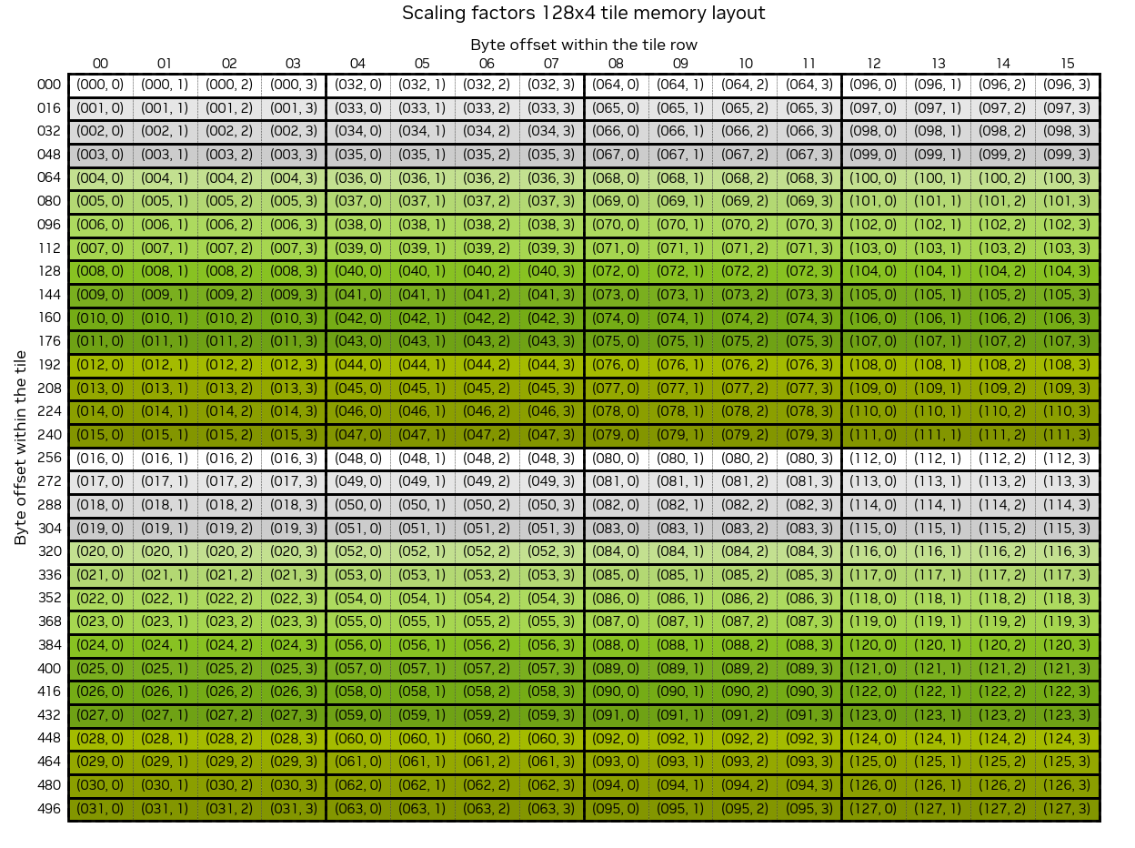
The above diagram depicts the logical 32 x 16 tile where the logical coordinates of the original 128 x 4 tile is shown within each cell.
Each of these subtiles then needs to be arranged into a contiguous tensor with the following layout:
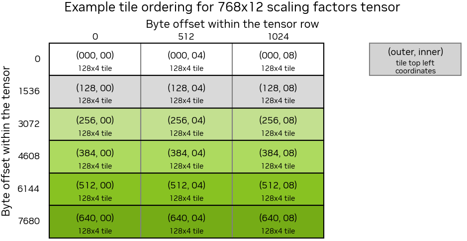
So the original tensor is carved into 128 x 4 subtensor blocks, each retiled to a 32 x 16 contiguous tile, then these subtensor blocks are flattened in row-major order.
Concretely:
# adapted from https://github.com/pytorch/pytorch/blob/638603aafeb4d9309952250b93a447722e1be248/torch/testing/_internal/common_quantized.py#L504-L535
def to_blockscale_format(t: torch.Tensor) -> torch.Tensor:
    """
    Rearrange tensor of scale factors into required blockscale layout.

    Args:
        t: Input tensor of shape (H, W)

    Returns:
        Rearranged tensor of shape (32*ceil_div(H,128), 16*ceil_div(W,4))
    """

    rows, cols = t.shape
    n_row_blocks = ceil_div(rows, 128)
    n_col_blocks = ceil_div(cols, 4)

    # Pad the tensor to `128 x 4` subtensors
    padded_rows = n_row_blocks * 128
    padded_cols = n_col_blocks * 4

    padded = t
    if (rows, cols) != (padded_rows, padded_cols):
        padded = torch.zeros((padded_rows, padded_cols), device=t.device, dtype=t.dtype)
        padded[:rows, :cols] = t

    # Reshape to blocks of `128 x 4` subtensors
    blocks = padded.view(n_row_blocks, 128, n_col_blocks, 4).permute(0, 2, 1, 3)
    # Reorder to contiguous `32 x 16` subtensors
    rearranged = blocks.reshape(-1, 4, 32, 4).transpose(1, 2).reshape(-1, 32, 16)

    # Return flattened subtensor blocks in row-major order
    return rearranged.flatten()
DGrad
The sequence of ops for DGrad is similar to FProp, but with in place of ; quantized inputs for were already calculated during FProp and cached for backward.
- uses the same fused kernels as to calculate , (saved for
WGrad), and . - The only notable difference is that requires stochastic rounding vs
RTNE. - , , and were already calculated during
FPropand saved to the autogradctx. - The same swizzling kernel and
cublasLtGEMM (with different transpose orientations) are then called to computeDGrad.
WGrad
For WGrad, we already have and from the fused amax kernel from FProp and DGrad, respectively.
Additionally, WGrad requires transposed with RHT + RTNE quantization and transposed with RHT + stochastic rounding.
This sequence of ops transpose → RHT → quantization to compute and or and is implemented in a single fused kernel, hadamard_transform_cast_fusion, which we'll discuss at length below.
Distributed NVFP4
Before we move on to the kernel deep dive, it's worth discussing how the NVFP4 quantization flow changes with tensor and sequence parallelism (TP / SP).
Under TP / SP, activations in forward and gradients in backward are sharded along the sequence dimension before column-parallel and row-parallel linears, respectively, and must be all-gathered.
Since it is more IO-efficient to quantize then gather, the computation flow must be adjusted to take into account the effect of quantization on local / global shapes.
FProp
For column-parallel forward GEMMs under TP / SP, the activations are first quantized then all-gathered. The issue with this order of ops is that the NVFP4 quantization requires a global scaling factor.
TE accounts for this by first calling the same local amax kernels we covered earlier and issuing an all-reduce immediately after the local amax has been computed. This is triggered by a flag in the Linear module when TP / SP is detected.
Since FProp requires rowwise quantization and inputs are sharded along "rows" under TP / SP, all-gathering a quantized tensor does not require reshaping after the collective.
While no reshaping is needed after an all-gather of a rowwise quantized input, there is a subtlety in the shapes of the local and gathered scale factors.
Specifically, blockwise GEMMs have strict layout requirements for scale factors and must be padded to multiples of 128 and 4 along dims 0 and 1, respectively. Since scale factors are first calculated – and padded – locally then all-gathered along dim 0, the gathered tensors would have incorrect padding along dim 0.
- Instead,
TEfirst removes padding along dim 0 and gathers into the full output shape ([padded_local_shape[0] * WORLD_SIZE, padded_local_shape[1]]) such that the gathered scale factors are correctly stacked, with padding only at the tail end of the entire gathered tensor.
DGrad
For row-parallel, rowwise-quantized DGrad under TP / SP, the gradient needs to be quantized then all-gathered as was the case for in FProp. The same set of flags triggers an all-reduce post local amax reduction.
WGrad
Recall that WGrad requires columnwise-quantized inputs and are computed immediately after rowwise quantization of the same tensor and cached ( during FProp and during DGrad). More importantly, these tensors are stored transposed.
For example, assuming has shape [M, K], then the columnwise tensor after quantization will be row-major [K, M // 2]; the factor of 2 comes from packing 2 FP4s into a single uint8_t.
The problem is that now the gathered tensor will be [WORLD_SIZE * K, M // 2], while what we want is a [K, WORLD_SIZE * (M // 2)] contiguous tensor.
To fix this incorrect interleaving of shards, the gathered tensor is effectively reshaped from [WORLD_SIZE * K, M // 2] → [WORLD_SIZE, K, M // 2] then permuted to a contiguous [K, WORLD_SIZE * (M // 2)] tensor post-gather using a custom kernel.
Columnwise quantization also complicates local to global redistribution of the scale factors.
Whereas we could unpad then gather into the full padded shape for rowwise scale factors, this would be incorrect for columnwise due to the need to reshape / permute the interleaved shards after the all-gather.
-
Instead,
TEremoves padding from both dimensions prior to the all-gather, then gathers into a trimmed empty tensor. -
After the all-gather and shape correction, the full fixed tensor is then re-padded.
Kernel Deep Dive
As we covered in the previous section, TransformerEngine implements custom kernels for many of the ops in the NVFP4 linear layer pipeline.
We'll cover one of these in depth: hadamard_transform_cast_fusion.
As we'll see, this kernel fuses many of the core ops in the quantization process:
Random hadamard transformon16 x 16tiles of the input tensor- Columnwise quantization and scale factor calculation
- Stochastic rounding
Moreover, it is a highly-specialized kernel written in CuTe / Cutlass specifically for sm100a.
The next section assumes knowledge of CUDA and CuTe / Cutlass.
Helpful background:
Fused Transposed Hadamard Quantization
As we covered earlier, the NVFP4 recipe requires different conditioning transforms for each of the GEMMs.
Recall that for WGrad:
- requires columnwise, round-to-nearest-even quantization with RHT.
- requires columnwise quantization with RHT and stochastic rounding.
Done naively, this would require multiple kernel launches and redundant data movement over mostly memory-bound kernels: transpose → RHT → quantization.
Instead, TransformerEngine folds these into a single kernel.
Overview
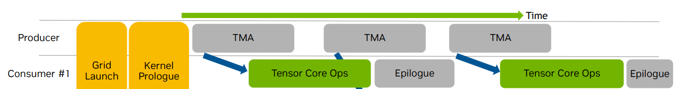
At a high-level, this kernel is warp-specialized, persistent, and architecture-specific:
- Warp-specialized: each warp in a threadblock does work specific to that warp in order to increase hardware utilization by asynchronously launching memory and compute ops.
- Persistent: number of threadblocks launched ≤ number of
SMssuch that each threadblock processes multiple tiles, as opposed to launching enough threadblocks to cover all tiles at once. - Architecture-specific: the kernel is specialized for datacenter Blackwell chips (
sm_100aandsm_103a). Specifically, stochastic rounding usingcvt.rswith destination typefp4e2m1is an architecture-specific instruction;TEchecks for this here. There are also hardcoded assumptions such assmemsize.
The kernel is structured as follows:
-
8 warps per CTA:
- 1 warp for DMA: reads input tensor, global amax, and hadamard matrix
- 1 warp for MMA: applies
RHTas a GEMM - 4 warps for the epilogue: performs quantization ±
SRand writes quantized output and scale factors out toGMEM - Remaining 2 warps do light work: 1 is used for initializing a
TMAbarrier for theRHTmatrix and the other does no warp-specific work.
-
2 pipelines for overlapping data movement and compute
- DMA -> MMA: multi-stage pipeline for overlapping copy-in of input tensor with
RHTcomputation- Each
CTAprocesses a128 x k_tile_sizestrip of the input tensor, wherek_tile_sizeis a heuristically set parameter (see below) in chunks of128 x 64(we'll unpack the logic for these shapes below). - Since this is a persistent kernel, each
CTAwill work on multiple such tiles during its lifetime.
- Each
- MMA -> Epilogue: 4-stage pipeline for overlapping the epilogue — quantization and copy-out of the quantized tensor and scale factors — with the
mma(RHTcomputation).
- DMA -> MMA: multi-stage pipeline for overlapping copy-in of input tensor with
Now let's step through this kernel, starting with the host code followed by a deep dive on the device code.
Note that in the source code snippets below, I've taken liberty in rearranging the code so that logically connected statements are grouped together. I've also added clarifying comments to help with interpretation of the code.
Host Code
The host code translates the high-level TransformerEngine pytorch API to parameters and arguments that the kernel can directly consume.
This is split into the following functions:
hadamard_transform_cast_fusion_columnwise: pre-conditions and high-level configrht_gemm_ttt_wrapper: wrapper function that flips orientation of GEMM fromtttontrht_gemm_ntt_w_sfc: translatesTEarguments toCutlass / CuTetypes and launches the kernel.
hadamard_transform_cast_fusion_columnwise
void hadamard_transform_cast_fusion_columnwise(const Tensor &input_, Tensor &output_,
                                               const Tensor &hadamard_matrix_,
                                               QuantizationConfig quant_config,
                                               cudaStream_t stream)
This function is the entrypoint and checks for the following pre-conditions:
-
input_: Input must bebfloat16and the input tensor must have rows divisible by the hardcodedhadamarddim (16).- Note that
input_is a non-transposedm x ntensor, which will later be loaded as ann x mtensor within the kernel and quantized alongm(hencecolumnwise).
- Note that
-
hadamard_matrix_: must be16 x 16for reasons covered earlier (matches theNVFP4block size).
The output_ tensor contains pre-allocated storage for the outputs of the kernel (quantized inputs and scale factors) and also the global_amax, which is needed for NVFP4 quantization.
The quant_config struct contains the rng states needed for stochastic rounding, set up earlier here.
The most important part of the setup code is the heuristic parameter k_tile_size set in the following code-block:
int k_tile_size = 1024;

if (m == 8192 && n == 5120) {
  k_tile_size = 512;
} else if (m == 8192 && n == 10240) {
  k_tile_size = 1024;
} else if (m == 8192 && n == 2560) {
  k_tile_size = 1280;
} else if (m == 8192 && n == 11328) {
  k_tile_size = 1024;
} else if (m == 8192 && n == 512) {
  k_tile_size = 256;
} else if (m == 8192 && n == 3584) {
  k_tile_size = 512;
} else if (m == 11328 && n == 8192) {
  k_tile_size = 1024;
}
...
This parameter tunes occupancy by setting the total number of columns (logical rows m since the tensor will be loaded as n x m by the kernel) that each CTA processes per output tile.
The smaller the k_tile_size, the thinner the "strip" of columns processed per output tile per CTA, and the more CTAs will be launched along n (up to num SMs). We'll make this more concrete once we get to the device code.
rht_gemm_ttt_wrapper
template <typename TA, typename TB, typename TC, typename TSFC, bool kEnableStochasticRounding = false>
void
rht_gemm_ttt_wrapper(int m, int n,
        TA const* A,
        TB const* B,
        TC      * C,
        TSFC    * SFC,
        float const* global_amax,
        const size_t* rng_state,
        uint32_t sm_count,
        cudaStream_t stream,
        int k_tile_size = 1024)
The ttt part of this wrapper function
refers to BLAS transposed notation.
m and n are the rows and columns of the input tensor.
Here A is the tensor to be quantized, B is the 16 x 16 hadamard matrix, C is the empty tensor for the quantized output, and SFC are the scale factors.
BLAS convention for GEMMs (omitting , , and for simplicity): .
A:M x Kcolumn-majorB:K x Ncolumn-majorD:M x Ncolumn-major
Here inputs and output are n or non-transposed so the GEMM would be considered nnn.
For a ttt gemm:
A:K x Mcolumn-majorB:N x Kcolumn-majorD:N x Mcolumn-major
The primary purpose of this wrapper is to call the kernel launcher rht_gemm_ntt_w_sfc with the rows (m) and cols (n) dims flipped for A so that the kernel sees the input matrix transposed.
This also explains the change in BLAS notation from ttt to ntt from wrapper to launcher.
rht_gemm_ntt_w_sfc<TA, TB, TC, TSFC, kEnableStochasticRounding>(
    n, m,
    A, B, C,
    SFC, global_amax,
    rng_state,
    sm_count, stream,
    k_tile_size);
rht_gemm_ntt_w_sfc
template <typename TA, typename TB, typename TC, typename TSFC, bool kEnableStochasticRounding = false>
void rht_gemm_ntt_w_sfc(int m, int n,
                        TA const* A,
                        TB const* B,
                        TC      * C,
                        TSFC    * SFC,
                        float const* global_amax,
                        const size_t* rng_state,
                        uint32_t sm_count,
                        cudaStream_t stream,
                        int k_tile_size = 2048)
rht_gemm_ntt_w_sfc translates TE NVFP4 args into Cutlass-compatible types.
Importantly, it is called with n and m are flipped relative to the original input tensor. This is so that the kernel sees the transposed tensor, and computes RHT and quantization along m (rows of the original tensor, columns of the transposed tensor).
The ntt notation also explains the expected input and output shapes:
A:n x mcolumn-major, which matches the contiguity of our original tensor (which wasm x nrow-major)B:16 x 16row-majorC:n x mrow-major, which matches the required contiguity of the downstream blockscale gemm where reduction will be alongm.
SFC will have shape n x (m // 16) – one scale factor per 16 element block.
Note that this is not a conventional GEMM, since we're transforming 16 x 16 blocks of A with the hadamard matrix, so the "output" of the GEMM will have the same logical shape as A.
Conceptually:
# A: n x m, H: 16 x 16
C = A.reshape(-1, 16) @ H
C = C.reshape(A.shape)
The primary purpose of rht_gemm_ntt_w_sfc is to set up the Cutlass / CuTe types and structs and launch the actual kernel.
Dtypes (hardcoded):
using TA = cute::bfloat16_t;
using TB = cute::bfloat16_t;
using TC = cutlass::float_e2m1_t;
using TSFC = cutlass::float_ue4m3_t;
Strides:
auto dA = make_stride(Int<1>{}, m);  // (dM,dK)
auto dB = make_stride(Int<1>{}, 16);  // (dN,dK)
auto dC = make_stride(n, Int<1>{});  // (dM,dN)
This matches our earlier discussion of expected input and output shapes and strides.
CuTe / Cutlass heavily leverages template metaprogramming and compile-tile C++ features for performance.
E.g.,
Int<1>and_1are compile-time constantsShape<_128, _64>is a templated type
As we'll see in upcoming sections, the tile shapes for memory and compute are all statically defined and many ops use tag / trait-based dispatch for zero-overhead abstraction.
Tiled MMA and Shared memory layout atoms
// Shapes for setting up mma and shared memory
auto cga_tile_shape = Shape<_128,_16,_16>{};
auto cluster_tile_mainloop = Shape<_128,_16,_64>{};

// TiledMMA struct
auto mma = make_tiled_mma(SM100_MMA_F16BF16_SS<TA, TB, float,
                                             128, 16,
                                             UMMA::Major::MN, UMMA::Major::MN>{},
                          Layout<Shape<_1,_1>>{});

// hadamard matrix
auto mma_shape_B = partition_shape_B(mma, make_shape(size<1>(cga_tile_shape), size<2>(cga_tile_shape)));

// Shared memory shapes
using SmemShape_M = decltype(shape_div(shape<0>(cga_tile_shape), shape_div(shape<0>(cga_tile_shape), size<0>(cga_tile_shape) / size(AtomThrID{}))));
using SmemShape_N = decltype(shape_div(shape<1>(cga_tile_shape), shape_div(shape<1>(cga_tile_shape), size<1>(cga_tile_shape) / size(AtomThrID{}))));
using SmemShape_K = decltype(cute::get<2>(cga_tile_shape));

// Swizzled shared memory atom for the hadamard matrix
using SmemLayoutAtomB = decltype(cutlass::gemm::collective::detail::sm100_smem_selector<
    cute::UMMA::Major::MN, TB, SmemShape_N, SmemShape_K>());

auto mma_shape_A = partition_shape_A(mma, make_shape(size<0>(cluster_tile_mainloop), size<2>(cluster_tile_mainloop)));

using SmemShape_M_A = decltype(shape_div(shape<0>(cluster_tile_mainloop), shape_div(shape<0>(cluster_tile_mainloop), size<0>(cluster_tile_mainloop) / size(AtomThrID{}))));
using SmemShape_K_A = decltype(cute::get<2>(cluster_tile_mainloop));

// Swizzled shared memory atom for input tensor
using SmemLayoutAtomA = decltype(cutlass::gemm::collective::detail::sm100_smem_selector<
    cute::UMMA::Major::MN, TA, SmemShape_M_A, SmemShape_K_A>());
The make_tiled_mma call sets up the specific mma operation to use, tiled to the specified shape (here just a single Shape<_1, _1>).
The specific instruction used here:
SM100_MMA_F16BF16_SS<TA, TB, float, 128, 16, UMMA::Major::MN, UMMA::Major::MN>
dispatches to the following trait and op.
In short, the trait encodes the metadata needed to execute the mma and the op contains the actual ptx instruction.
Here the ptx instruction is tcgen05.mma.cta_group::1.kind::f16:
- 5th generation tensor core mma
- Launched by a single thread
- 1
CTAmma (see CTA Pair) BF16operands,FP32accumulator
The template params are:
TA,TB,float: dtypes of operands and accumulator / output128,16:MandNof the GEMM.Kis implicitly16, as statically determined here.
So basically, this matches the hadamard transform mma.
The shared memory layout setup calls:
cutlass::gemm::collective::detail::sm100_smem_selector<
    cute::UMMA::Major::MN, TB, SmemShape_N, SmemShape_K>()
This sets up a "layout atom", which describes how the tensor will be layed out in shared memory after TMA copy.
Based on the strides, data type and shapes, the "selector" determines the widest suitable swizzle for the TMA transfer and the "core" units that comprise this swizzled layout. Briefly, swizzling can be thought of as offsetting logical columns across logical rows to prevent shared memory bank conflicts which serializes memory access.
This information is then checked by the downstream mma call when constructing the shared memory descriptors.
See shared memory layout and canonical layouts for more details.
Moving on to the structs for B:
smemShapeN: _16
smemShapeK: _16
mma_shape_B: ((_16,_16),_1,_1)
SmemLayoutAtomB: Sw<1,4,3> o smem_ptr[16b](unset) o (_16,_8):(_1,_16)
This corresponds to a 32B MN-major swizzle with a 2 x 8 "swizzle atom layout" in 128b units, or equivalently 16 x 8 in bf16 elements.
Similarly, for A, the tensor to be quantized (either activation or gradient tensor):
SmemShape_M_A: _128
SmemShape_K_A: _64
mma_shape_A: ((_128,_16),_1,_4)
smemLayoutAtomA: Sw<3,4,3> o smem_ptr[16b](unset) o (_64,_8):(_1,_64)
So the shared memory layout is 128 x 64 in units of 128B-swizzled 64 x 8 layout atoms, contiguous along M.
Important to note is the shape of mma_shape_A: the tiled_mma struct will interpret the 128 x 64 shared memory as 4 128 x 16 individual A operands.
Together with the layout of B, we now understand:
- We're loading the hadamard matrix into shared memory (
16 x 16), swizzled to limit bank conflicts - Copying
128 x 64tiles of the input tensor intosmemin larger swizzled units, again for efficient loading - For each
128 x 64input tile, we will perform 4128 x 16 x 16mma's.
Next full shared memory layouts are set up based on the earlier layout atoms:
constexpr int kBlackwellSmemSize = 232448; // 232KB in bytes
constexpr int kBytesPerStage = cute::size(mma_shape_A) * sizeof(TA) + cute::size(mma_shape_B) * sizeof(TB);
constexpr int kReservedBytes = 256; // Reserve for barriers and other uses
constexpr int kMaxStages = (kBlackwellSmemSize - kReservedBytes) / kBytesPerStage;
auto sP = Int<kMaxStages>{};      // SMEM pipelines
auto sA = UMMA::tile_to_mma_shape(SmemLayoutAtomA{}, append(mma_shape_A, sP)); // (MMA,MMA_M,MMA_K,PIPE)
auto sB = UMMA::tile_to_mma_shape(SmemLayoutAtomB{}, append(mma_shape_B, sP)); // (MMA,MMA_N,MMA_K,PIPE)
...
int smem_size = sizeof(SharedStorage<TA, TB, decltype(sA), decltype(sB)>);
Printing sA and sB, we can view their layouts:
sA: Sw<3,4,3> o smem_ptr[16b](unset) o (((_64,_2),(_8,_2)),_1,_4,(_1,_13)):(((_1,_512),(_64,_1024)),_0,_2048,(_0,_8192))

sB: Sw<1,4,3> o smem_ptr[16b](unset) o ((_16,_16),_1,_1,(_1,_13)):((_1,_16),_0,_0,(_0,_256))
Let's unpack the shape of sA to understand how the TMA engine will load A from gmem → smem.
From left to right:
((_64,_2),(_8,_2)): This matches the original shape128 x 16but sliced into 264 x 8tiles – these are the "atomic"MN-major128Bswizzled TMA atoms._1, _4: we have 4 of these128 x 16tiles(_1, _13): we have 13 pipeline stages.
sB can be interpreted the same way. One thing to note is that we are doing a single 16 x 16 load of the matrix despite the MN-major 32B swizzled TMA atom having shape 16 x 8. This is because the two sub-tiles will be situated contiguously in smem, so a single coalesced load works in this case.
kMaxStages refers to the DMA -> MMA pipeline stages, which will be configured to maximize pipeline depth by using all shared memory remaining after reserving space for barriers and other necessary smem structs.
The final shared memory buffers for A and B are the previous mma_shapes appended with the number of pipeline stages. For B this is ((16, 16),...,13) where 13 the number of stages that can fit on a B200.
Next, TMA descriptors are constructed:
// Create GMEM tensors
Tensor tensorA = make_tensor(A, make_layout(make_shape(M,N), dA));      // (M,N)
Tensor tensorB = make_tensor(B, make_layout(make_shape(16,16), dB));      // (16,16)

// TMA TiledCopy structs
auto tma_load_a = make_tma_copy_A_sm100(
      SM90_TMA_LOAD{},
      tensorA,
      sA(_,_,_,0),
      cluster_tile_mainloop,
      mma);
auto tma_load_b =  make_tma_copy_B_sm100(
      SM90_TMA_LOAD{},
      tensorB,
      sB(_,_,_,0),
      cga_tile_shape,
      mma);
The tma_load_a and tma_load_b structs encapsulate the TMA tensor maps and also provide convenience functions for copying the global tensors.
The arguments for the tma_copy struct:
SM90_TMA_LOADstruct encodes theptxglobal -> sharedTMAload instruction, which will dispatch to the 2-D variant given the shapes of the tensors.tensorAandtensorBare the global memory pointerssAandsBare the shared memory tensors. Needed to infer theswizzleparameter andbox sizesforTMAtensor map.mmais theTiledMMAstruct which affects theTMAcopy depending on whether themmais1-smor2-sm.
Finally, the launch config is set:
uint32_t tiles = size(ceil_div(M, get<0>(cga_tile_shape))) * size(ceil_div(N, k_tile_size));

tiles = (tiles < sm_count) ? tiles : sm_count;

dim3 dimBlock(256);
dim3 dimCluster(size<0>(cga_shape), size<1>(cga_shape), size<2>(cga_shape));
dim3 dimGrid(tiles, 1, 1);
Note how k_tile_size, which we covered earlier is used to determine the launch grid.
Recall that the rows and cols of the activation tensor were reversed since we're quantizing the transpose, so M corresponds to logical columns of the original tensor and N the logical rows.
This means that we're tiling by 128 along rows (logical cols) and along cols (logical rows).
We'll use an activation tensor with original shape 8192 x 5120 to make things concrete.
- So
k_tile_size = 512from the heuristic - For
B200,sm_count = 148, sotilesis capped at148.
In short, the launch config:
- Threads: 1D threadblock with
blockDim.x = 256, so8warps perCTA - ThreadBlocks: 1D grid with
gridDim.x = tiles - Clusters:
cga_tile_shapeis hardcoded asShape<_1, _1, _1>, so no CGA.
That wraps up host side kernel setup. Before moving to the device code, a quick recap of the kernel host-side setup:
- Constructed
TiledMmastruct for performing the128 x 16 x 16hadamard transform GEMM - Created
TMA(swizzled) tensor maps for both operands - Configured shared memory pipeline buffers for the activation tensor and hadamard matrix
- These buffers reflect the compute shapes per pipeline stage:
4GEMMs with shape128 x 16 x 16 - Multi-stage pipeline with number of stages maxing out shared memory (so at most 1
CTAperSM) - Remember this is a persistent kernel – so each
CTAstays resident on anSMfor the duration of the kernel - This design amortizes the cost of kernel prologue / pipeline set up and also suits the data movement pattern of the kernel (hadamard matrix only needs to be loaded once).
- These buffers reflect the compute shapes per pipeline stage:
- Launch grid of
148threadblocks (for example shape8192 x 5120) and8warps per threadblock.
Device Code
template <class MShape, class NShape, class KShape, class ClusterTileShape,
          class TA, class AStride, class ASmemLayout, class TmaLoadA,
          class TB, class BStride, class BSmemLayout, class TmaLoadB,
          class TC, class CStride, class CSmemLayout,
          class TSFC,
          class TiledMMA,
          bool kEnableStochasticRounding = false>
__global__ static
void
rht_gemm_device(MShape M, NShape N, KShape K, ClusterTileShape cluster_tile,
            TA const* A, AStride dA, ASmemLayout sAlayout, CUTE_GRID_CONSTANT TmaLoadA const tma_load_a,
            TB const* B, BStride dB, BSmemLayout sBlayout, CUTE_GRID_CONSTANT TmaLoadB const tma_load_b,
            TC      * C, CStride dC, CSmemLayout         ,
            TSFC    * SFC,
            TiledMMA mma,
            float const* global_amax,
            const size_t* rng_state)
The device code is structured into a prologue, which all warps execute, and warp-specialized DMA, MMA, and epilogue loops.
Prologue
The kernel prologue sets the stage for the kernel, defining variables and preparing data structures that will be consumed by the Mainloop and Epilogue.
The prologue roughly falls into these sections:
- Warp Assignments – assign warps to their specific task
- Shared Memory – setup tensors for slicing / partitioning
smem - Pipelines – construct mainloop and accumulator pipelines
- Tile Schedule – CTA-level tile indexing
- DMA prep – prepare tensors and variables for
TMAtransactions - MMA prep – set up TiledMMA,
smemdescriptor, andtmemaccumulator tensors - Epilogue prep – construct
tmemtensors and allocator struct
The structure above is my interpretation of the prologue logic, the original source is not ordered the same but has the same overall logical intent.
Warp Assignments
bool is_mma_warp = (warp_idx == 0);
bool is_dma_warp = (warp_idx == 1);
bool is_epilogue_warp = (warp_idx >= 4 && warp_idx <= 7);
Here, we see warps being specialized for the following roles:
- Data loading: the
DMAwarp will continuously load data from global memory to shared memory using theTMAengine - Computation: the
MMAwarp will continuously issuerhtGEMMs on the loaded data - Epilogue: the epilogue warpgroup will quantize the
rht-conditioned tiles and store the encoded tiles and scale factors to global memory.
Recall we launched with 8 warps.
- One of these remaining warps (warp 2) is used only to initialize the barrier for loading the hadamard matrix.
- The other (warp 3) is not used.
My guess is that this kernel was adapted from a Cutlass GEMM template.
For example, the sm100_gemm_tma_warpspecialized Cutlass template has the following enum:
enum class WarpCategory : int32_t {
  MMA          = 0,
  Sched        = 1,
  EpilogueLoad = 3,
  Epilogue     = 4,
  MainloopLoad = 8
};
Notably, only the MMA, Epilogue and MainloopLoad roles are needed for this kernel.
Schedis needed only when using the CLC tile schedulerEpilogueLoadis needed only for loading auxiliary data (i.e., the in )
Shared Memory
Shared memory buffers are set up at the start:
extern __shared__ char shared_memory[];
using SharedStorage = SharedStorage<TA, TB, ASmemLayout, BSmemLayout>;
SharedStorage& shared_storage = *reinterpret_cast<SharedStorage*>(shared_memory);
Tensor tCsA = make_tensor(make_smem_ptr(shared_storage.tensors.smem_A.data()), sAlayout);  // (MMA,MMA_M,MMA_N,PIPE)
Tensor tCsB = make_tensor(make_smem_ptr(shared_storage.tensors.smem_B.data()), sBlayout);  // (MMA,MMA_N,MMA_K,PIPE)
sAlayout and sBlayout are the swizzled, pipelined layouts we covered earlier, and tCsA and tCsB are views into smem with these respective indexing schemes.
Their shapes and strides for one threadblock:
// These layouts are uniform across threadblocks except for the pointer address
tCsA: Sw<3,4,3>_smem_ptr[16b](0x7fe600000580) o (((_64,_2),(_8,_2)),_1,_4,(_1,_13)):(((_1,_512),(_64,_1024)),_0,_2048,(_0,_8192))
tCsB: Sw<1,4,3>_smem_ptr[16b](0x7fe600034580) o ((_16,_16),_1,_1,(_1,_13)):((_1,_16),_0,_0,(_0,_256))
The SharedStorage struct stores the auxiliary data structures used across warps of the CTA:
template <class ElementA, class ElementB, class ASmemLayout, class BSmemLayout>
struct SharedStorage {
  static constexpr int AccumulatorPipelineStageCount = 16;
  using AtomThrShapeMNK = cute::Shape<_1, _1, _1>;

  using AccumulatorPipeline =
      cutlass::PipelineUmmaAsync<AccumulatorPipelineStageCount / 4, AtomThrShapeMNK>;
  using AccumulatorPipelineStorage = typename AccumulatorPipeline::SharedStorage;

  static constexpr int MainloopPipelineStageCount = size<3>(ASmemLayout{});
  using MainloopPipeline = cutlass::PipelineTmaUmmaAsync<MainloopPipelineStageCount,
                                                        Shape<_1, _1, _1>, AtomThrShapeMNK>;
  using MainloopPipelineStorage = typename MainloopPipeline::SharedStorage;

  alignas(16) AccumulatorPipelineStorage accumulator;
  alignas(16) MainloopPipelineStorage mainloop;
  alignas(16) cute::uint64_t tma_barrier[1];
  uint32_t tmem_base_ptr;

  struct TensorStorage : cute::aligned_struct<128, _1> {
      cute::array_aligned<ElementA, cute::cosize_v<ASmemLayout>> smem_A;
      cute::array_aligned<ElementB, cute::cosize_v<BSmemLayout>> smem_B;
  } tensors;
};
We can see that shared memory is used for:
-
Staging Buffers:
smem_Aandsmem_Bare the pipelined buffers we discussed earlier. -
Barriers:
MainloopPipelineStorageandAccumulatorPipelineStorageare used to store the barriers required for coordinating async data movement and compute across warps (and CTAs).
Peeking into the SharedStorage types of these structs:
struct SharedStorage {
  FullBarrier full_barrier_[Stages];
  EmptyBarrier empty_barrier_[Stages];
};
The roles of the barrier pair will become clearer when we cover pipelines – the tldr is that the full barrier is used by the producer warp to signal to the consumer warp(s) when a payload has been transferred and is safe to use, and the empty barrier is used to signal that the consumer warp is done using the payload and that the buffer for that stage can be used for a subsequent load.
- For the
MainloopPipeline, the producer is theDMAwarp (the one doing theTMAloading) and the consumer is theMMAwarp (the one computing the RHT) - For the
AccumulatorPipeline, the producer is theMMAwarp and the consumers are the epilogue warps (the ones doing the quantization and store back to theGMEM).
The additional tma_barrier is used for the single load of the hadamard matrix, which does not need to be pipelined.
tmem_base_ptr we'll see later, but for now, know that it is used to store the base pointer to the tensor memory allocation.
Pipeline Setup
Mainloop Pipeline: DMA -> MMA
static constexpr int MainloopPipelineStageCount = size<3>(ASmemLayout{});
// Define the pipeline type, number of stages is a compile-time constant
using MainloopPipeline = cutlass::PipelineTmaUmmaAsync<MainloopPipelineStageCount,
                                                      Shape<_1, _1, _1>, AtomThrShapeMNK>;
using MainloopPipelineState = typename MainloopPipeline::PipelineState;

typename MainloopPipeline::Params mainloop_pipeline_params;
if (is_dma_warp) {
  mainloop_pipeline_params.role = MainloopPipeline::ThreadCategory::Producer;
}
if (is_mma_warp) {
  mainloop_pipeline_params.role = MainloopPipeline::ThreadCategory::Consumer;
}

// Only the leader thread in the dma warp will issue TMA loads
mainloop_pipeline_params.is_leader = cute::elect_one_sync() && is_dma_warp;
mainloop_pipeline_params.transaction_bytes = kTmaTransactionBytes;
mainloop_pipeline_params.initializing_warp = 0;

// Create the pipeline struct: initializes mbarriers for each stage of the pipeline
MainloopPipeline mainloop_pipeline(shared_storage.mainloop,
                                     mainloop_pipeline_params,
                                     cluster_shape,
                                     cute::true_type{},   // Perform barrier init
                                     cute::true_type{}); // Delay mask calculation

MainloopPipelineState mainloop_pipe_consumer_state;
// Producer starts at opposite phase as the consumer state since EmptyBarriers are empty at the start
MainloopPipelineState mainloop_pipe_producer_state = cutlass::make_producer_start_state<MainloopPipeline>();
The purpose of this pipeline is to coordinate TMA loads (producer) with tcgen05 mma's (consumer) since both are asynchronous instructions issued by single threads in separate warps.
Essentially we want to ensure that data is always at the ready so that tensor cores are crunching continuously.
A few notes:
MainloopPipelineStateis a utility struct used to track the states of the producer (FullBarrier) and consumer (EmptyBarrier) barriers. We'll see how it is used when we get to theDMA/MMAloops.- The
make_producer_start_stateinitializes the mainloopDMAproducer with a phase of 1 since thesmembuffers are empty at init.
- The
MainloopPipelineconstructor call initializes thembarriersbacking theFullBarrierandEmptyBarrierpairs for each stage of the pipeline.- The
producerandconsumerarrival counts are both1, since no multicasting is used and theTMAandtcgen05.mmainstructions are both single-thread launches.
Note that the pipeline is specialized for tcgen05 (Umma) – this is because the synchronization mechanisms for tcgen05 differ from prior generations.
Accumulator Pipeline: MMA -> Epilogue
The purpose of this pipeline is to sync the mma warp (producer) with the epilogue warps (consumers).
- The
epiloguewarps need to wait for themmacompletion before using a pipelinedtmemaccumulator buffer. - The
mmawarp, in turn, must wait for the epilogue warps to finish using a stage of thetmembuffer before accumulating into that pipeline stage.
static constexpr int AccumulatorPipelineStageCount = 16;
using AtomThrShapeMNK = cute::Shape<_1, _1, _1>;

// Define the pipeline type, number of stages is set at compile-time
using AccumulatorPipeline = cutlass::PipelineUmmaAsync<AccumulatorPipelineStageCount / 4, AtomThrShapeMNK>;
using AccumulatorPipelineState = typename AccumulatorPipeline::PipelineState;

// Create pipeline states: producer starts with opposite phase as consumers since buffers are empty at start
AccumulatorPipelineState accumulator_pipe_consumer_state;
AccumulatorPipelineState accumulator_pipe_producer_state = cutlass::make_producer_start_state<AccumulatorPipeline>();

typename AccumulatorPipeline::Params accumulator_pipeline_params;
if (is_mma_warp) {
  accumulator_pipeline_params.role = AccumulatorPipeline::ThreadCategory::Producer;
}
if (is_epilogue_warp) {
  accumulator_pipeline_params.role = AccumulatorPipeline::ThreadCategory::Consumer;
}
// Only one producer thread
accumulator_pipeline_params.producer_arv_count = 1;
// 128 consumer threads
accumulator_pipeline_params.consumer_arv_count = size(AtomThrShapeMNK{}) * 128;
accumulator_pipeline_params.initializing_warp = 1;
// Construct pipeline and initialize barriers
AccumulatorPipeline accumulator_pipeline(shared_storage.accumulator,
                                         accumulator_pipeline_params,
                                         cluster_shape,
                                         cute::true_type{},   // Perform barrier init
                                         cute::true_type{}); // Delay mask calculation
A few things to note:
- Arrival counts: The
producerarrival count is 1, sincetcgen05.mmahas single-thread semantics; theconsumerarrival count is 128, since the entire epilogue warpgroup participates in reading fromtmem.
Note that the AccumulatorPipeline is defined with a 4-stage pipeline whereas the MainloopPipeline used the maximum number of stages that fit in smem, which for the dtypes and shapes for this kernel is ~13. (See the definition of the AccumulatorPipeline type not the confusingly named AccumulatorPipelineStageCount variable).
As we'll see later in the epilogue setup, these buffers occupy half of the available space in tmem.
The difference in pipeline depths could be the relative producer / consumer loads:
AccumulatorPipeline: the epilogue (consumer) is relatively heavy compared to the mma (producer), since the epilogue warps must transfer accumulator values fromtmem→rmem, quantize (using CUDA cores), then store fromrmem→gmem, whereas themmadoes 4 smallish GEMMs per stage using high-throughput tensor cores. Also, max'ing outtmemwould only double the number of stages from 4 to 8.MainloopPipeline: as we covered earlier, we want the tensor cores to be constantly fed, so it makes sense to set up a deep pipeline fromdma→mma.
Tile Schedule
The tile schedule sections sets up the tile indices for mapping gmem tiles to threadblocks.
// Global tile grid
const int K_TILE_MAX = min(N, K) / 64;
uint32_t tiles_in_m = (M + size<0>(cluster_tile) - 1) / size<0>(cluster_tile);
uint32_t tiles_in_n = (N + 64 - 1) / 64;

// CTA tile indices
uint32_t linear_tile_idx = blockIdx.x;
uint32_t tile_idx_m = linear_tile_idx % tiles_in_m;
uint32_t tile_idx_n = (linear_tile_idx / tiles_in_m) * K_TILE_MAX;
Mapping these to our example 8192 x 5120 input tensor:
Nis8192Kis set tok_tile_size, which for the input shape is512according to the heuristic we covered earlier
The cluster_tile is 128 x 16 x 16, so tiles_in_m = 40 and tiles_in_n = 128.
With a 1D launch grid with 148 threadblocks:
- Stripes of
K_TILE_MAXtiles of shape128 x 64will be assigned in round-robin fashion alongM - Once a
CTAis finished with thisK_TILE_MAX*128 x 64stripe of tiles, it will be assigned another such stripe, strided by grid-dim (148).
With these indexes established, we'll see how they're used to partition global tensors.
auto mainloop_tiler = Shape<_128, _16, _64>{};
auto epilogue_tiler = Shape<_128, _64, _64>{};

// Input activation tensor
Tensor gA_mk = local_tile(mA, mainloop_tiler, make_coord(_, _, _), Step<_1, X, _1>{});

// Hadamard matrix
Tensor gB_nk =
    local_tile(mB, cluster_tile, make_coord(_, _, _), Step<X, _1, _1>{});  // (BLK_N,BLK_K,k)

// Output (quantized) tensor
Tensor gC_mn =
    local_tile(mC, epilogue_tiler, make_coord(_, _, _), Step<_1, _1, X>{});  // (BLK_M,BLK_N)

// Scale factors
Tensor gSFC_mn =
    local_tile(mSFC, epilogue_tiler, make_coord(_, _, _), Step<_1, _1, X>{});  // (BLK_M,BLK_N)
The Step parameter and X placeholder indicate which modes of the tensor to slice, so Step<_1, X, _1> means to slice only along modes 0 and 2.
The ArithTuple abstraction is for representing CuTe tensors in a TMA-friendly way. See tma tensors for more info.
mA and mB are the input tensor (5120 x 8192, transposed view of our original tensor) and hadamard matrix (16 x 16) in global memory. The purpose of local_tile is to slice these tensors into per-CTA views
Printing out these tensors, we get:
gA_mk: ArithTuple(_0,_0) o (_128,_64,40,128):(_1@0,_1@1,_128@0,_64@1)
gB_nk: ArithTuple(_0,_0) o (_16,_16,1,1):(_1@0,_1@1,_16@0,_16@1)
gC_mn: subptr[4b](0x7fe562000000.0) o (_128,_64,40,128):(8192,_1,1048576,_64)
gSFC_mn: gmem_ptr[8b](0x7fe55e000000) o (_128,(_16,_4),40,128):(512,(_0,_1),65536,_4)
We're now able to address our global tensors by CTA coordinate by indexing along the 2nd and 3rd modes – gA_mk(_, _, 1, 0) would give us the global offset into the input tensor at the logical index (128, 0).
Note the shape and stride of gSFC_mn:
- The inner shape is
128 x (16, 4)so the total size is the same as the inner shape of the input tensor, yet we know that quantization is in blocks of size16per theNVFP4spec – i.e., for a128 x 64tile quantized along the 2nd mode, there should be(128 x (64 // 16))scale factors. - The resolution: the stride for this sub-tensor is
(512, (_0,_1))– that is, we're assigning a stride of 0 to the mode with dim16. This is equivalent to broadcasting the same value along this mode, which allows us to view the scale factors as the same logical shape as the input tensor, but with physical offsets to the actual number of scale factors (4for this shape).
DMA Prep
  static constexpr int K_PIPE_MAX = size<3>(ASmemLayout{});
  using AtomThrShapeMNK = Shape<decltype(shape<0>(typename TiledMMA::ThrLayoutVMNK{})), _1, _1>;

  static constexpr uint32_t kTmaTransactionBytes =
  cutlass::bits_to_bytes(size(AtomThrShapeMNK{}) * cosize(take<0,3>(ASmemLayout{})) * cute::sizeof_bits_v<TA>);

  static constexpr int kTmaRhtTensorTransactionBytes =
  cutlass::bits_to_bytes(16 * 16 * cute::sizeof_bits_v<TB>);
ASmemLayout has layout: Sw<3,4,3> o smem_ptr[16b](unset) o (((_64,_2),(_8,_2)),_1,_4,(_1,_13)):(((_1,_512),(_64,_1024)),_0,_2048,(_0,_8192)). Ignoring the swizzle and stride, we see that the shape is (((_64,_2),(_8,_2)),_1,_4,(_1,_13)).
-
The first part
((_64,_2),(_8,_2))is themmaoperandAshape128 x 16, split into 264 x 8atomic swizzled TMA loads. The_1, _4part indicates we're doing 4 of these, since we want to load a128 x 64Atile per stage. -
The remaining
(_1, _13)or simply_13is the number of pipeline stages for theDMA -> MMApipeline, which recall was set to max out the shared memory perCTA. -
AtomThrShapeMNKis 1 (would be 2 if we were doing a2-smmma)
This means the TMA transaction bytes is 128 * 16 * 4 * 2 = 16384 for the activation tensor and 16 * 16 * 2 = 512 for the hadamard matrix.
There are a few more steps in setting up tensors for DMA, which we'll cover in the next section, as there are a few concepts we need to cover first.
MMA Setup
There are two main functions accomplished in this section:
- TMA tensors — reslice the global tensors to layouts compatible for
TMAandTiledMmaconsumption. - UMMA descriptors — create "tensors" for the descriptors needed for
UMMA
TMA tensors
First, the threadblock-level view of A and B are converted to a mma-centric view:
  ThrMMA thr_mma = mma.get_slice(block_rank_in_cluster);

  Tensor tCgA = thr_mma.partition_A(gA_mk);
  Tensor tCgB = thr_mma.partition_B(gB_nk);
gA_mk and gB_nk are the CTA-level views of A and B:
gA_mk:  ArithTuple(_0,_0) o (_128,_64,40,128):(_1@0,_1@1,_128@0,_64@1)
gB_nk:  ArithTuple(_0,_0) o (_16,_16,1,1):(_1@0,_1@1,_16@0,_16@1)
After partitioning, we get tCgA and tCgB:
tCgA:   ArithTuple(_0,_0) o ((_128,_16),_1,_4,40,128):((_1@0,_1@1),_0,_16@1,_128@0,_64@1)

tCgB:   ArithTuple(_0,_0) o ((_16,_16),_1,_1,1,1):((_1@0,_1@1),_0,_0,_16@0,_16@1)
Same underlying pointers, just different ways of indexing them.
Next, these tensors can be used to create the gmem and smem tensors that can be used directly for TMA copy:
  auto [tAgA, tAsA] = tma_partition(tma_load_a,
    get<2>(cta_coord_vmnk), make_layout(size<2>(cta_layout_vmnk)),
    group_modes<0,3>(tCsA), group_modes<0,3>(tCgA));

  auto [tBgB, tBsB] = tma_partition(tma_load_b,
    get<1>(cta_coord_vmnk), make_layout(size<1>(cta_layout_vmnk)),
    group_modes<0,3>(tCsB), group_modes<0,3>(tCgB));
The layouts for these tensors:
tAgA:   ArithTuple(_0,_0) o (((_64,_8),(_2,_8)),40,128):(((_1@0,_1@1),(_64@0,_8@1)),_128@0,_64@1)
tAsA:   Sw<3,4,3>_smem_ptr[16b](0x7f2a00000580) o ((_512,_16),(_1,_13)):((_1,_512),(_0,_8192))

tBgB:   ArithTuple(_0,_0) o (((_16,_16),_1),1,1):(((_1@0,_1@1),_0),_16@0,_16@1)
tBsB:   Sw<1,4,3>_smem_ptr[16b](0x7fb000034580) o ((_256,_1),(_1,_13)):((_1,_0),(_0,_256))
From the above layouts, we see that these tensors now represent the TMA atoms discussed earlier, which will be transferred from gmem and layed out contiguously in smem.
UMMA Descriptors
tcgen05.mma requires two types of descriptors: shared memory descriptors and instruction descriptors.
- Shared memory descriptors define the layout and addresses of the
AandBoperands. - Instruction descriptors describe the type of
mma: dtypes, shape, transposes, etc.
First the shared memory descriptors are created, wrapped in CuTe's tensor abstraction:
  Tensor tCrA = thr_mma.make_fragment_A(tCsA);
  Tensor tCrB = thr_mma.make_fragment_B(tCsB);
The textual representation of these tensors:
tCrA:   UMMA::DescriptorIterator o (_1,_1,_4,(_1,_13)):(_0,_0,_256,(_0,_1024))
tCrB:   UMMA::DescriptorIterator o (_1,_1,_1,(_1,_13)):(_0,_0,_0,(_0,_32))
So for the 4 128 x 16 x 16 UMMA ops, we have 4 descriptors for A and 1 for B per pipeline stage.
Now let's unpack what make_fragment_{A,B} is doing under the hood to create these DescriptorIterators.
thr_mma inherits MMATraits<SM100_MMA_F16BF16_SS<...>>, which defines the following fragment types:
template <class a_type, class b_type, class c_type,
          int M, int N, UMMA::Major a_major, UMMA::Major b_major,
          UMMA::ScaleIn a_neg, UMMA::ScaleIn b_neg>
struct MMA_Traits<SM100_MMA_F16BF16_SS<a_type, b_type, c_type,
                                M, N, a_major, b_major,
                                a_neg, b_neg>>
{
  ...
  using FrgTypeA = UMMA::smem_desc<a_major>;
  using FrgTypeB = UMMA::smem_desc<b_major>;
  ...
};
These fragment types function as tag-based policies for tensor creation.
In this case, the specialization is a tensor backed by a DescriptorIterator, an iterator over the shared memory descriptors consumed by tcgen05.mma instructions.
The tensors returned by make_fragment_A and make_fragment_B provide a way to "index" a tensor of shared memory descriptors.
These shared memory descriptors are uint64_t values consumed by UMMA with the following prescribed schema:
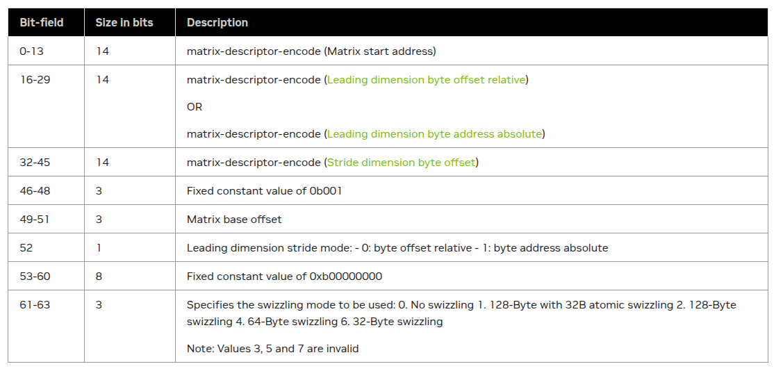
This structure is mirrored by Cutlass, with the notable fact that it separates the 64 bits into upper and lower 32-bit fields.
union SmemDescriptor
{
  uint64_t desc_ = 0;
  // Bitfield implementation avoids the need for shifts in assignment
  struct {
    // start_address, bit [0,14), 4LSB not included
    uint16_t start_address_ : 14, : 2;                     // 14 bits [0,14), 2 bits unused
    // leading dimension byte offset, bit [16,30), 4LSB not included
    uint16_t leading_byte_offset_ : 14, : 2;               // 14 bits [0,14), 2 bits unused
    // stride dimension byte offset, bit [32,46), 4LSB not included
    uint16_t stride_byte_offset_ : 14, version_ : 2;       // 14 bits [0,14), 2 bits [14,16)
    // base_offset, bit [49,52). leading_byte_offset_mode, bit [52,53).
    uint8_t : 1, base_offset_ : 3, lbo_mode_ : 1, : 3;     // 1 bit unused, 3 bits [1,4), 1 bit [4,5), 3 bits unused
    // layout type, bit [61,64), SWIZZLE_NONE matrix descriptor = 0, SWIZZLE_128B matrix descriptor = 2, SWIZZLE_64B descriptor = 4, SWIZZLE_32B descriptor = 6, SWIZZLE_128B_BASE32B = 1, N/A = 3, N/A = 5, N/A = 7
    uint8_t : 5, layout_type_ : 3;                         // 6 bits unused, 3 bits [5,8)
  };
  // Separate the field, as we may only update one part of desc
  struct {
    uint32_t lo;
    uint32_t hi;
  };

  // Decay to a uint64_t
  CUTE_HOST_DEVICE constexpr
  operator uint64_t() const noexcept { return desc_; }
};
DescriptorIterator provides a way to "index" this descriptor.
struct DescriptorIterator
{
  using reference    = SmemDescriptor;
  using element_type = SmemDescriptor;
  using value_type   = SmemDescriptor;

  SmemDescriptor desc_;

  // Dereference returns the UmmaDescriptor
  CUTE_HOST_DEVICE constexpr
  reference operator*() const { return desc_; }

  // Advance and return a new UmmaDescriptor
  template <class Index>
  CUTE_HOST_DEVICE constexpr
  reference operator[](Index const& i) const { return *(*this + i); }

  // Return an advanced iterator
  template <class Index>
  CUTE_HOST_DEVICE constexpr
  DescriptorIterator operator+(Index const& offset) const
  {
    // Use 32bit calculation rather than 64 bit calculation as we only update the part of desc
    SmemDescriptor ret;
    ret.lo = desc_.lo + uint32_t(offset);
    ret.hi = desc_.hi;
    return { ret };
  }
};
As we can see, "indexing" a descriptor iterator simply creates a new SmemDescriptor by updating the lower 32 bits of the previous descriptor, which stores the shared memory address of the tensor; the upper 32 bits are kept constant since we're using the same underlying shared memory tensor with the same layout properties, just at a different offset.
With the shared memory descriptors created, let's move on to the UMMA Instruction Descriptor.
UMMA Instruction Descriptor
Technically, the descriptor was already created when we created the TiledMma struct in the host code setup.
The descriptor is completely defined by the MMA_Traits specialization for the MMA_Op that was selected SM100_MMA_F16BF16_SS<TA, TB, float, 128, 16, UMMA::Major::MN, UMMA::Major::MN>.
The descriptor schema is encoded in Cutlass as:
union InstrDescriptor
{
  uint32_t desc_;

  struct {
    // Bitfield implementation avoids the need for shifts in assignment
    uint16_t sparse_id2_    : 2,  // bit [ 0, 2) : Sparse meta data id2
             sparse_flag_   : 1,  // bit [ 2, 3) : 0 = dense. 1 = sparse. 1 value valid only for F32F16/S8/MXF8F6F4
             saturate_      : 1,  // bit [ 3, 4) : 0 = no saturate. 1 = saturate. 1 value valid only for S8
             c_format_      : 2,  // bit [ 4, 6) : 0 = F16. 1 = F32, 2 = S32
                            : 1,  //
             a_format_      : 3,  // bit [ 7,10) : MXF8F6F4Format:0 = E4M3, 1 = E5M2, 3 = E2M3, 4 = E3M2, 5 = E2M1. F32F16Format: 0 = F16, 1 = BF16, 2 = TF32. S8: 0 unsigned 8 bit, 1 signed 8 bit. Boolean MMA: 0 Boolean
             b_format_      : 3,  // bit [10,13) : MXF8F6F4Format:0 = E4M3, 1 = E5M2, 3 = E2M3, 4 = E3M2, 5 = E2M1. F32F16Format: 0 = F16, 1 = BF16, 2 = TF32. S8: 0 unsigned 8 bit, 1 signed 8 bit. Boolean MMA: 0 Boolean
             a_negate_      : 1,  // bit [13,14) : 0 = no negate. 1 = negate. 1 value valid only for F32F16Format and MXF8F6F4Format
             b_negate_      : 1,  // bit [14,15) : 0 = no negate. 1 = negate. 1 value valid only for F32F16Format and MXF8F6F4Format
             a_major_       : 1;  // bit [15,16) : 0 = K-major. 1 = MN-major. Major value of 1 is only valid for E4M3, E5M2, INT8 (signed and unsigned), F16, BF16 and TF32 source formats
    uint16_t b_major_       : 1,  // bit [16,17) : 0 = K-major. 1 = MN-major. Major value of 1 is only valid for E4M3, E5M2, INT8 (signed and unsigned), F16, BF16 and TF32 source formats
             n_dim_         : 6,  // bit [17,23) : 3 LSBs not included. Valid values range from 1 (N=8) to 32 (N=256). All values are not valid for all instruction formats
                            : 1,  //
             m_dim_         : 5,  // bit [24,29) : 4 LSBs not included. Valid values are: 4 (M=64), 8 (M=128), 16 (M=256)
                            : 1,  //
             max_shift_     : 2;  // bit [30,32) : Maximum shift for WS instruction. Encoded as follows: 0 = no shift, 1 = maximum shift of 8, 2 = maximum shift of 16, 3 = maximum shift of 32.
  };

  // Decay to a uint32_t
  CUTE_HOST_DEVICE constexpr explicit
  operator uint32_t() const noexcept { return desc_; }
};
In the constructor of the MMA_Traits, the descriptor is directly encoded from the template parameters of our specialized op:
template <class a_type, class b_type, class c_type,
          int M, int N, UMMA::Major a_major, UMMA::Major b_major,
          UMMA::ScaleIn a_neg = UMMA::ScaleIn::One, UMMA::ScaleIn b_neg = UMMA::ScaleIn::One,
          UMMA::Saturate c_sat = UMMA::Saturate::False,
          bool is_sparse = false,
          UMMA::MaxShift max_shift = UMMA::MaxShift::NoShift>
CUTE_HOST_DEVICE constexpr
UMMA::InstrDescriptor
make_instr_desc()
{
  UMMA::InstrDescriptor desc_i = {};

  desc_i.a_format_ = uint8_t(UMMA::to_UMMAFormat<a_type>());
  desc_i.b_format_ = uint8_t(UMMA::to_UMMAFormat<b_type>());
  desc_i.c_format_ = uint8_t(UMMA::to_CFormat<c_type>());

  desc_i.m_dim_ = (M >> 4);
  desc_i.n_dim_ = (N >> 3);

  desc_i.a_major_ = uint8_t(a_major);
  desc_i.b_major_ = uint8_t(b_major);

  desc_i.a_negate_ = uint8_t(a_neg);
  desc_i.b_negate_ = uint8_t(b_neg);
  desc_i.saturate_ = uint8_t(c_sat);

  desc_i.sparse_flag_   = is_sparse;    // 1 = Sparse
  desc_i.sparse_id2_    = 0;

  desc_i.max_shift_ = uint8_t(max_shift);

  return desc_i;
}
In addition to the shared memory and instruction descriptors, there is one more argument that needs to be setup for the MMA mainloop — the tmem tensors that will serve as the accumulators of the mma op, which we will cover in the next section.
Epilogue Setup
The epilogue needs to
- load from
tmemaccumulators intormem - perform quantization (either
RTNEorSR) - store the results to
gmem.
The epilogue setup prepares the structures needed for these steps by converting the mma tmem accumulators into a layout that can be used to copy to rmem and computed on efficiently.
To do this, a "dummy" TiledMMA is used to retile the results of the main TiledMMA performed by the MMA warp to a vectorized view more conducive to thread-level computation. Note that this epilogue mma struct is used solely to do this tensor slicing and not for actual computation.
First, the code, then we'll walk through the logic:
  // Create "dummy" TiledMma
  auto mma_epilogue = make_tiled_mma(SM100_MMA_F16BF16_SS<TA, TB, ElementAccumulator,
                                               128, 64,
                                               UMMA::Major::MN, UMMA::Major::MN>{},
                            Layout<Shape<_1,_1>>{});
  ThrMMA thr_mma_epilogue = mma_epilogue.get_slice(block_rank_in_cluster);


  using TiledMmaEpilogue = decltype(mma_epilogue);

  // Define mma shapes from mma and epilogue perspectives
  auto acc_shape_mma = partition_shape_C(TiledMMA{}, take<0,2>(ClusterTileShape{}));
  auto acc_shape_epilogue = partition_shape_C(TiledMmaEpilogue{}, take<0,2>(epilogue_tiler));

  // Make `tmem` accumulator tensors with mma and epilogue-specific layouts
  auto bulk_tmem_mma = TiledMMA::make_fragment_C(append(acc_shape_mma,
                                                      Int<AccumulatorPipelineStageCount>{}));
  auto bulk_tmem_epilogue = TiledMmaEpilogue::make_fragment_C(append(acc_shape_epilogue,
                                                      Int<AccumulatorPipelineStageCount / 4>{}));
Recall that the main TiledMMA that actually does the RHT computation was defined as:
SM100_MMA_F16BF16_SS<TA, TB, float, 128, 16, UMMA::Major::MN, UMMA::Major::MN>{},
                            Layout<Shape<_1,_1>>
The key difference is the N dimension, 16 in the actual computation and 64 in the "fake" mma.
acc_shape_mma:      ((_128,_16),_1,_1)
acc_shape_epilogue: ((_128,_64),_1,_1)
In contrast to earlier GPU generations which accumulated to rmem, Blackwell tcgen05.mma accumulates to tmem, so the make_fragment_C call is a specialized path that creates a tensor-like view of tmem.
We can see this in the MMA_Traits for SM100_MMA_F16BF16_SS:
template <class a_type, class b_type, class c_type,
          int M, int N, UMMA::Major a_major, UMMA::Major b_major,
          UMMA::ScaleIn a_neg, UMMA::ScaleIn b_neg>
struct MMA_Traits<SM100_MMA_F16BF16_SS<a_type, b_type, c_type,
                                M, N, a_major, b_major,
                                a_neg, b_neg>>
{
  ...

  using FrgTypeA = UMMA::smem_desc<a_major>;
  using FrgTypeB = UMMA::smem_desc<b_major>;
  using FrgTypeC = UMMA::tmem_frg_1sm<c_type>;

  ...
}
The fragment type for operand C is UMMA::tmem_frg_1sm<c_type>:
template <class ValueType, class StorageType = uint32_t, UMMA::TmemAllocMode TmemAlloc = UMMA::TmemAllocMode::Interleaved>
using tmem_frg_1sm = tmem_frg<ValueType, StorageType, 1, TmemAlloc>;
The base type tmem_frg defines a make method that is the dispatch destination of make_fragment_C.
The purpose of this method is to create a tensor-like view of tmem.
Tensor memory (tmem) is a per-CTA 256KB memory space with 128 rows (data-paths) and 512 columns of 32b cells.
- Addresses are
uint32_twith the lower 16 bits used for indexing columns and upper 16 bits for rows (not all bits are used given the dimensions oftmem) - Access is restricted by warp such that a full warpgroup is needed to access all of 128 rows: warp 0 can access rows 0 - 31, warp 1 32-63, etc.

The make_fragment_C call returns the following tensors:
bulk_tmem_mma:      tmem_[32b](0x0000.0000) o ((_128,_16),_1,_1,_16):((_65536,_1),_0,_0,_16)
bulk_tmem_epilogue: tmem_[32b](0x0000.0000) o ((_128,_64),_1,_1,_4):((_65536,_1),_0,_0,_64)
These tensors will alias the same slice of tmem:
bulk_tmem_mmawill be used as theaccumulatorargument to thetcgen05.mmainstruction by theMMAwarpbulk_tmem_epiloguewill then be used by the epilogue warps to get an aggregated view of the slice before copying fromtmem→rmem.
More specifically,
- each
mmais128 x 16 x 16, so we need to provide addresses to128 x 16slices oftmemfor eachmmaop - we perform 4 of these
mmas perAccumulatorPipelinestage - we have 4 total pipeline stages, hence the
_16and_4dimensions in thebulk_tmemtensors.
In short, the output that the epilogue warpgroup sees per pipeline stage is ((128 x 16) x 4), which it needs to copy out as a single 128 x 64 using CuTe's TiledCopy abstraction.
The bulk_tmem_mma and bulk_tmem_epilogue tmem tensors have an innermost layout (_128, _16):(_65536, _1) and (_128, _64):(_65536, _1). This is a row-major layout where stepping along rows advances by 1 "unit" and along cols by 65536 "unit".
Where is the 65536 coming from and what are the "units" of this tensor?
Recall that tensor memory addressing is represented by an uint32_t that must index 128 data path lanes (rows) and 512 column lanes (columns).
| Dim | Bits (MSB→LSB) | Width | Range | Active Mask |
|---|---|---|---|---|
| Lane index | 31–16 | 16 | 128 | 0x007F |
| Column index | 15–0 | 16 | 512 | 0x01FF |
In order for the tmem tensor to compose with Cutlass / CuTe mma / copy algorithms, indexing the tensor should return an offset into an underlying pointer-like object.
The tmem tensor is backed by a tmem_ptr, "a typed, word-addressed, non-dereferenceable pointer" which must represent an uint32_t with the above addressing scheme.
template <class T>
struct tmem_ptr
  ...

  CUTE_HOST_DEVICE constexpr
  tmem_ptr operator+(uint32_t const& i) const {
    return {addr_ + rotr(i, OffsetShift)};    // Rotate the offset to keep subword indices in the unused high 8bits for debug
  }

  // TMEM "Address" with active mask 0x007F.01FF
  // The upper 16 bits, the 0x007F portion, refers to the 128  DP lanes
  // The lower 16 bits, the 0x01FF portion, refers to the 512 COL lanes
  union {
    uint32_t addr_;
    struct {
      uint16_t col_;
      uint8_t  dp_;
      uint8_t  idx_;
    };
  };
So the tmem_ptr essentially stores an uint32_t address with the expected dp and col fields and returns a fresh instance with new address upon integer addition. rotr (rotate right) and OffsetShift are used to normalize different data types under a common indexing scheme; for float, OffsetShift=0, so rotr(i, OffsetShift) simply returns i.
Indeed if we index into bulk_tmem_mma as an example:
| Index | Address |
|---|---|
bulk_tmem_mma(_,_,_, 0) | tmem_[32b](0x0000.0000) |
bulk_tmem_mma(1, _, _, 0) | tmem_[32b](0x0001.0000) |
bulk_tmem_mma(2, _, _, 0) | tmem_[32b](0x0002.0000) |
bulk_tmem_mma(128, _, _, 0) | tmem_[32b](0x0000.0001) |
bulk_tmem_mma(256, _, _, 0) | tmem_[32b](0x0000.0002) |
bulk_tmem_mma(_, _, _, 1) | tmem_[32b](0x0000.0010) |
bulk_tmem_mma(_, _, _, 2) | tmem_[32b](0x0000.0020) |
We can now understand the bulk_tmem_mma layout ((_128,_16),_1,_1):((_65536,_1),_0,_0):
- The
bulk_tmem_mmais representing a128 x 256slice oftmemin 4128 x 16slices. - Within each
128 x 16slice, indexing along the 0'th mode indexes thedplane and 1st mode thecollane- Remember that
CuTeuses column-major order, which is why the flat coordinate128→collane 1,256→collane 2;1→dplane 1,2→dplane 2.
- Remember that
- In order to calculate the correct address, when indexing along a
dplane, we need to shift by 16 to set the correct bits:1 << 16 = 65536.- E.g.
bulk_tmem_mma(2, _, _, 0)→2 * 65536 = 0x0002.0000
- E.g.
- When indexing across slices, we shift the
collane by 16- E.g.,
bulk_tmem_mma(_, _, _, 1)→1 * 16 = 0x0000.0010 - As we'll see later in the
mmaloop, this is the indexing pattern used to shift accumulator addresses for each128 x 16 x 16RHTGEMMs.
- E.g.,
bulk_tmem_mma and bulk_tmem_epilogue provide a tensor-like view of tmem.
tmem still needs to be allocated, which is the next part of the epilogue setup:
  using TmemAllocator = cute::TMEM::Allocator1Sm;
  TmemAllocator tmem_allocator{};
  cutlass::arch::NamedBarrier tmem_allocation_result_barrier(32 + 128, cutlass::arch::ReservedNamedBarriers::TmemAllocBarrier);
Allocator1Sm is a thin wrapper for managing tmem, and exposes methods for calling the ptx instructions for allocating, freeing, and relinquishing tmem.
NamedBarrier is a utility struct for calling bar instructions on a hardware barrier (8 reserved by Cutlass, 16 total), and will be used to sync tmem allocation between the MMA and epilogue warps.
The final part of the epilogue setup is to define the type of tcgen05.ld op to copy the mma accumulators from tmem to rmem for quantization.
using TMEM_LOAD_NEW = cute::SM100::TMEM::LOAD::SM100_TMEM_LOAD_32dp32b64x;
This type is a wrapper around the ptx instruction tcgen05.ld.sync.aligned.32x32b.x64.b32:
tcgen05.ld— load fromtmem→rmemsync(mandatory) — the executing thread waits for all other threads in warp to execute the same instruction before continuingaligned(mandatory) — all threads in the warp must execute the same instruction32x32b— the shape:32data path lanes,32bbitwidth across columnsx64— number of units
So each warp in the epilogue warpgroup will copy a 32 x 64 tile from tmem, covering the entire 128 x 64 accumulator tile.
The thread-value mapping will resemble the following after the load, with each thread owning 64 32b values instead of the x1 and x2 loads shown below:
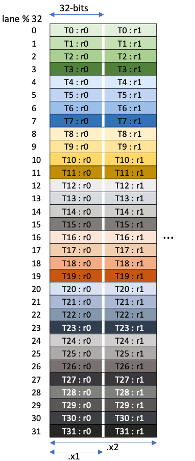
Kernel Mainloop
Now that the prologue is complete, we are ready to dive into the meat of the kernel: the DMA, MMA, and Epilogue.
All warps have a similar nested loop structure:
do {
  // Set up data structures for main work loop
  ...
  while (k_tile < K_TILE_MAX && k_tile + tile_idx_n < tiles_in_n){
    // Main work loop
    // Each iteration works on `128 x 64` tile
    ...
  }
  // Advance to next `(128 x 64) x K_TILE_MAX` tile of global tensor
  linear_tile_idx += gridDim.x;
  tile_idx_m = linear_tile_idx % tiles_in_m;
  tile_idx_n = (linear_tile_idx / tiles_in_m) * K_TILE_MAX;
} while (tile_idx_m < tiles_in_m && tile_idx_n < tiles_in_n);
// Teardown / cleanup
...
The outer loop is the persistent schedule, fetching the next (128 x 64) x K_TILE_MAX tile to work on, while the inner loop iterates over the K_TILE_MAX tiles, processing a 128 x 64 subtile per iteration in the main work loop.
The main workloop by warp role:
TMAloads for theDMAwarpRHTgemm for theMMAwarp- Quantization + stores for the epilogue warpgroup
Before and after each warp performs warp-specific setup and teardown.
DMA
The DMA warp starts by loading the RHT matrix once.
if (is_dma_warp) {
  if (elect_one_sync()) {
    cute::set_barrier_transaction_bytes(shared_storage.tma_barrier[0], kTmaRhtTensorTransactionBytes);
    copy(tma_load_b.with(shared_storage.tma_barrier[0], tma_mcast_mask_b), tBgB(_,0,0), tBsB(_,0));
  }
  cute::wait_barrier(shared_storage.tma_barrier[0], 0 /*tma_phase_bit*/);
A single thread issues the 512 byte TMA load from gmem → smem, then the entire warp blocks until arrival.
Next, the DMA warp enters the previously described loop structure, loading a global (128 x 64) x K_TILE_MAX tile in chunks of 128 x 64 before advancing to the next tile.
do {
    bool is_first_wave = linear_tile_idx == blockIdx.x;
    uint32_t skip_wait = is_first_wave;
    auto tAgA_mk = tAgA(_,tile_idx_m,_);
    int k_tile = 0;

    // Get completion status of the EmptyBarrier for the current stage
    auto barrier_token = mainloop_pipeline.producer_try_acquire(mainloop_pipe_producer_state, skip_wait);

    CUTE_NO_UNROLL
    while (k_tile < K_TILE_MAX && k_tile + tile_idx_n < tiles_in_n) {
      int k_tile_idx_n = tile_idx_n + k_tile;
      ++k_tile;
      skip_wait = (is_first_wave && k_tile < MainloopPipelineStageCount);

      // Blocking wait on EmptyBarrier for the current pipeline producer stage then
      // arrive and expect on current load
      mainloop_pipeline.producer_acquire(mainloop_pipe_producer_state, barrier_token);

      // Get the FullBarrier for current pipeline producer stage
      using BarrierType = typename MainloopPipeline::ProducerBarrierType;
      BarrierType* tma_barrier = mainloop_pipeline.producer_get_barrier(mainloop_pipe_producer_state);

      // Record current stage to write to then advance to next stage
      int write_stage = mainloop_pipe_producer_state.index();
      ++mainloop_pipe_producer_state;

      // Get barrier token for next stage
      barrier_token = mainloop_pipeline.producer_try_acquire(mainloop_pipe_producer_state, skip_wait);

      // TMA load `128 x 64` tile for current stage of producer pipeline
      if (cute::elect_one_sync()) {
        copy(tma_load_a.with(*tma_barrier, tma_mcast_mask_a), tAgA_mk(_,k_tile_idx_n), tAsA(_,write_stage));
      }
    }
    // Advance to next tile
    linear_tile_idx += gridDim.x;
    tile_idx_m = linear_tile_idx % tiles_in_m;
    tile_idx_n = (linear_tile_idx / tiles_in_m) * K_TILE_MAX;
  } while (tile_idx_m < tiles_in_m && tile_idx_n < tiles_in_n);

  // Drain pipeline, wait for consumer warp to finish using buffers
  mainloop_pipeline.producer_tail(mainloop_pipe_producer_state);
}
Here we can see the mainloop pipeline at work:
- Each loop iteration, the
DMAproducer warp acquires a barrier token for the current EmptyBarrier (the barrier that the consumer warp arrives on).- Under the hood,
producer_try_acquireissues atry_waiton theEmptyBarriermbarrierand returns the completion status.
- Under the hood,
- Within the loop, the
producer_acquire:- blocks until the
MMAwarp is finished using the pipeline producer stage by waiting on theEmptyBarrier. - After the wait is complete, the leader thread in the
DMAwarp then arrives and sets the transaction bytes for the incoming128 x 64tile on theFullBarrierfor the current stage.
- blocks until the
- The current
FullBarrierand stage are extracted before advancing the pipeline to the next stage - Finally, the current
FullBarrierand stage are then used to TMA load fromgmeminto the current stage'ssmembuffer.- The
MMAwarp, as we'll see below, will wait on this barrier for the arrival of transaction bytes set inproducer_acquirebefore using this slice of thesmembuffer.
- The
After the DMA producer has finished loading tiles, it waits for all consumer warps to finish using loaded tiles by waiting on all EmptyBarriers to flip. This is to ensure in multicast scenarios (not directly relevant for this kernel) that this CTA does not exit before other CTAs in the cluster are done using the shared tile.
MMA
The MMA warp starts by allocating tmem before entering its main workloop:
if (is_dma_warp){
  ...
}
else if (is_mma_warp) {
  // Allocate `tmem`
  tmem_allocator.allocate(TmemAllocator::Sm100TmemCapacityColumns, &shared_storage.tmem_base_ptr);

  // Ensure allocation is complete and that the allocated address has been written to shared memory
  __syncwarp();

  // Signal to the epilogue warpgroup that allocation is complete
  tmem_allocation_result_barrier.arrive();

  // Point the accumulator tensor to the base address of the allocated `tmem`
  uint32_t tmem_base_ptr = shared_storage.tmem_base_ptr;
  bulk_tmem_mma.data() = tmem_base_ptr;
  ...
  //Start main workloop
  do {
    ...
  } while (...)
}
The warp reserves the maximum number of tmem columns (512) and ensures memory-ordering by issuing a bar.warp.sync before signaling to the epilogue warpgroup (tmem_allocation_result_barrier.arrive) and setting the accumulator tensor's base address to the allocated address.
Next, the MMA's main workloop:
do {
  uint32_t skip_wait = K_TILE_MAX <= 0;
  // Poll the FullBarrier for the completion of TMA
  auto barrier_token = mainloop_pipeline.consumer_try_wait(mainloop_pipe_consumer_state, skip_wait);

  // Process K_TILE_MAX `128 x 64` tiles
  CUTE_NO_UNROLL
  for (int k_tile = 0; k_tile < K_TILE_MAX && k_tile + tile_idx_n < tiles_in_n; )
  {
    // Block until TMA load completes on FullBarrier for the current stage
    mainloop_pipeline.consumer_wait(mainloop_pipe_consumer_state, barrier_token);

    // Get the current pipeline stage
    int read_stage = mainloop_pipe_consumer_state.index();

    // Tensor view into the `128 x 64` `smem` buffer for the current pipeline stage
    auto tCrA_mk = tCrA(_,_,_,read_stage);

    // Hadamard matrix – constant across iterations
    auto tCrB_nk = tCrB(_,_,0,0);

    // Note that size<2>(tCrA) is always 4, so this outer loop exits after a single iteration
    CUTE_UNROLL
    for (int k_block = 0; k_block < size<2>(tCrA) / 4; ++k_block)
    {
      // Wait on the EmptyBarrier of the current stage of the **accumulator** pipeline
      accumulator_pipeline.producer_acquire(accumulator_pipe_producer_state);

      // Apply RHT to 128 x 16 tiles of the input tensor 4x
      CUTE_UNROLL
      for (int i = 0; i < 4; i++) {
        auto accumulators = bulk_tmem_mma(_,_,_,accumulator_pipe_producer_state.index() * 4 + i);
        gemm(mma, tCrA_mk(_,_,k_block * 4 + i), tCrB_nk, accumulators);
      }
      // Issue a `tcgen05.commit` for current batch of mmas on the FullBarrier of current accumulator pipeline stage
      accumulator_pipeline.producer_commit(accumulator_pipe_producer_state);
      ++accumulator_pipe_producer_state;
    }
    auto curr_mainloop_pipe_consumer_state = mainloop_pipe_consumer_state;
    ++mainloop_pipe_consumer_state;
    ++k_tile;
    skip_wait = k_tile >= K_TILE_MAX;

    // Poll FullBarrier for the next stage of the mainloop pipeline
    barrier_token = mainloop_pipeline.consumer_try_wait(mainloop_pipe_consumer_state, skip_wait);

    // Issue a ` tcgen05.commit` for current batch of mmas on the EmptyBarrier of the current stage of the mainloop pipeline
    mainloop_pipeline.consumer_release(curr_mainloop_pipe_consumer_state);
  }
  // Advance to the next tile
  linear_tile_idx += gridDim.x;
  tile_idx_m = linear_tile_idx % tiles_in_m;
  tile_idx_n = (linear_tile_idx / tiles_in_m) * K_TILE_MAX;
} while (tile_idx_m < tiles_in_m && tile_idx_n < tiles_in_n);
The MMA needs to synchronize with both the DMA warp and the epilogue warpgroup in its workloop.
Whereas the MMA warp is the consumer in the mainloop pipeline, it plays the role of producer in the accumulator pipeline:
- It must poll and wait on the
FullBarrierof the current mainloop pipeline stage to ensure the full128 x 64tile has arrived insmem - UMMADescriptor tensors are created for the current MMA operands from the
128 x 64slice of thesmembuffer for the current pipeline stage and the16 x 16RHTslice ofsmem(constant across iterations) - Before the warp can start issuing
tcgen05.mmainstructions, it must first wait on theEmptyBarrierof the current accumulator pipeline stage.- This happens when all threads in the epilogue warpgroup arrive on this barrier to indicate that they have finished transferring the accumulators from
tmemtormemand that this stage oftmemis safe to accumulate into.
- This happens when all threads in the epilogue warpgroup arrive on this barrier to indicate that they have finished transferring the accumulators from
- Once the barrier has flipped, the
MMAwarp starts issues 4tcgen05.mmainstructions, storing the results in 4128 x 16slices oftmem.- Recall that the
bulk_tmem_mmatensor has 16 "stages", each corresponding to a128 x 16slice oftmem. - 4 of these "stages" (4
128 x 16 x 16mmas) correspond to 1 stage of the 4-stage accumulator pipeline - This is done for reasons of efficiency, as the epilogue warpgroup can bulk process
128 x 64accumulators at a time, rather than sync'ing every128 x 16slice.
- Recall that the
- These 4 mmas are grouped into a single tcgen05.commit on the
FullBarrierof the accumulator pipeline.- The epilogue warpgroup will then wait on this barrier to flip (occurs when all the
tcgen05.mmainstructions in the commit group complete) before starting work on the correspondingtmemaccumulators.
- The epilogue warpgroup will then wait on this barrier to flip (occurs when all the
- After the 4 mmas for the current
128 x 64tile has been issued and committed on the accumulator pipelineFullBarrier, this batch of mmas still needs to be committed on the mainloop pipeline to signal to theDMAwarp when thesmembuffer that the mmas consume is safe to write to.- This is done within
mainloop_pipeline.consumer_release, which issues atcgen05.commiton theEmptyBarrierof the current mainloop pipeline stage. (This pairs with theproducer_try_waitandproducer_waitwe saw earlier in theDMAloop).
- This is done within
After the MMA warp has finished processing tiles, it performs 3 important cleanup duties:
do {
  // MMA main workloop
  ...
} while(...)

// Relinquish `tmem` alloc permission
tmem_allocator.release_allocation_lock();
// Wait for epilogue warpgroups to finish using `tmem`
accumulator_pipeline.producer_tail(accumulator_pipe_producer_state);
// Free tmem
tmem_allocator.free(tmem_base_ptr, TmemAllocator::Sm100TmemCapacityColumns);
...
First, it relinquishes tmem allocation rights. Next it waits for the accumulator pipeline to drain, much like the DMA warp waited for the consumers of the mainloop pipeline to complete.
Finally, once the epilogue warpgroup has signalled all pipeline stages of the tmem buffer has been transferred to rmem, the MMA is able to deallocate tmem.
Epilogue
The epilogue warpgroup does the bulk of the quantization work.
It has the same outer / inner loop structure as the DMA / MMA warps, where each outer loop starts a new row of K_TILE_MAX 128 x 64 subtiles and the inner loop pipelines the processing of these K_TILE_MAX subtiles.
An iteration of the epilogue inner loop consists of:
- Load
mmaresults fromtmem→rmem - Quantize the
floataccumulators tofp4e2m1andfp8e4m3scale factors - Store the quantized results from
rmem→gmem
Before the epilogue warpgroup enters its workloop, it first waits for the tmem allocation from the MMA warp to complete:
  if (is_dma_warp){ ...}
  else if (is_mma_warp) { ... }
  else if (is_epilogue_warp) {
    const float global_amax_val = *global_amax;
    static constexpr int FragmentSize = 256 / sizeof_bits_v<TC>;

    tmem_allocation_result_barrier.arrive_and_wait();
    ...

  }
arrive_and_wait calls bar.sync under the hood, which causes the executing thread to wait for arrival of all threads participating in the barrier (32 from MMA warp, 128 from epilogue warpgroup) – this is in contrast to the MMA warp, where the warp only needs to wait for arrival of threads in its warp. Both serve the purpose of ensuring that tmem allocation completes before read / write.
The same synchronization pattern is also present in the canonical SM100 warp-specialized Cutlass kernel.
Load from tmem to registers
Before entering the inner loop, the copy structs for performing the tcgen05.ld are instantiated:
    uint32_t tmem_base_ptr = shared_storage.tmem_base_ptr;
    bulk_tmem_epilogue.data() = tmem_base_ptr;
    int thread_idx = threadIdx.x % 128;

    // Set up `tmem` -> `rmem` TiledCopy
    auto tiled_t2r = make_tmem_copy(TMEM_LOAD_NEW{}, bulk_tmem_epilogue(_,_,_,_0{}));
    // Get thread-level thread-value mapping
    auto thr_t2r   = tiled_t2r.get_slice(thread_idx);
tile_t2r is an abstraction for performing tiled copies from tmem → rmem:
TMEM_LOAD_NEWis defined as typeSM100_TMEM_LOAD_32dp32b64x, which instructs each warp in the warpgroup to load a32 x 64tile fromtmem.bulk_tmem_epiloguehas shape((_128,_64),_1,_1,_4), so indexing by0along the 4th mode (pipeline stage) gives a128 x 64shaped tensor.tiled_t2rand its thread-level instantiationthr_t2rthen perform the necessary calculations to create source and destination thread-value mappings.- For the
32dp32b64xvariant oftcgen05.ld, this mapping is straightforward, since each thread in the warpgroup owns one data path of6432bcolumn values.
Then within the inner loop, the warpgroup waits for the mma for the current accumulator pipeline stage to complete (consumer_wait dispatches to the mbarrier.try_wait) before copying the tmem accumulators into registers.
    // Wait for mma to complete
    accumulator_pipeline.consumer_wait(accumulator_pipe_consumer_state);

    // Slice out current stage of accumulator pipeline buffer
    auto tCtC = bulk_tmem_epilogue(_,_,_,accumulator_pipe_consumer_state.index());
    Tensor tDtC = thr_t2r.partition_S(tCtC);
    Tensor tDgC = thr_t2r.partition_D(tCgC_mn);

    // Create `rmem` fragment for storing accumulators
    Tensor tTR_rAcc = make_tensor<ElementAccumulator>(shape(tDgC));

    // Copy from `tmem` to `rmem`
    copy(tiled_t2r, tDtC, tTR_rAcc);

    // Fence the async copy to ensure memory ordering
    cutlass::arch::fence_view_async_tmem_load();

    // Signal to the mma warp that safe to re-use pipeline buffer for this stage
    accumulator_pipeline.consumer_release(accumulator_pipe_consumer_state);

    // Advance pipeline state
    ++accumulator_pipe_consumer_state;
Since tcgen05.ld is asynchronous, the load from tmem needs to be synchronized. Here, fence_view_async_tmem_load is an inline ptx call to tcgen05.wait::ld.sync.aligned, which causes the executing thread to wait until the load completes and for all threads in its warp to execute the wait before continuing.
The threads in the epilogue warpgroup then arrive on the EmptyBarrier of the current accumulator_pipeline stage by calling consumer_release, signalling to the MMA warp that it has finished reading from this tmem buffer stage, before advancing the pipeline state to the next stage (++accumulator_pipe_consumer_state).
If we print out the textual representations for the tensors involved in the tmem tiled copy, we get:
tCtC:   tmem_[32b](0x0000.0000) o ((_128,_64),_1,_1):((_65536,_1),_0,_0)
tDtC:   tmem_[32b](0x0000.0000) o (((_64,_32),_1),_1,_1,_1):(((_1,_65536),_0),_0,_0,_0)
tTR_rAcc:       ptr[32b](0x7f5b75fffa20) o ((_64,_1),_1,_1,_1):((_1,_0),_0,_0,_0)
tCtC is a "global" view of the tile of tmem we're going to partition and copy from. tTR-rAcc is simply an array of 64 registers.
The important bit is tDtC, which serves as the tmem source of the copy.
If we print out tDtC for all warps in the epilogue warpgroup (eliding the layout since they are the same for all warps):
| warp ID | tmem address |
|---|---|
| 0 | tmem_[32b](0x0000.0000) |
| 1 | tmem_[32b](0x0020.0000) |
| 2 | tmem_[32b](0x0040.0000) |
| 3 | tmem_[32b](0x0060.0000) |
This makes sense from our earlier discussion of tmem addressing and tmem access restrictions:
thr_t2ris partitioning the sourcetmemtensor by warp, sincetcgen05.ldhas warp-level semantics- Each warp in the epilogue warpgroup is issuing a
tcgen05.ldinstruction, and must pass thetmemaddress of the data path offset to the 32 lanes it "owns" to the instruction tmemaccess by warp ID in a warpgroup per the ptx docs is as follows:
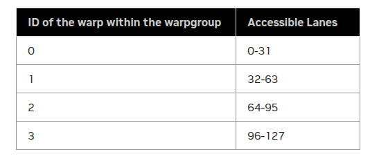
Quantization
Before performing the actual quantization, we need to first reshape and recast the register fragments for efficient vectorized access and compute.
We start by defining tensor views into the output buffers for storing the quantized values and scale factors.
  // Tile-level views of the output buffers for storing quantized values and scale factors
  Tensor tCgC_mn = tCgC(_,_,_,tile_idx_m,tile_idx_n+k_tile);
  Tensor tCgSFC_mn = gSFC_mn(_,_,tile_idx_m,tile_idx_n+k_tile);
tCgC:   subptr[4b](0x7f8046000000.0) o ((_128,_64),_1,_1,40,128):((8192,_1),_0,_0,1048576,_64)
tCgC_mn:        subptr[4b](0x7f2bce000000.0) o ((_128,_64),_1,_1):((8192,_1),_0,_0)
Next we create registers for storing the fp4e2m1 results and recast the accumulator registers:
  // Prepare fragments (registers) for converting FP32 accumulators to FP4

  /**
    NOTE:
    - `tDgC` is the thread-level view of the output tensor used for `tmem` -> `rmem` tiled copy.
    - `tTR_rACC` is the destination tensor that the accumulators were copied into. See `tmem` -> `rmem` copy above.
    - `TC` = quantized data type (fp4e2m1)
  **/
  Tensor tDrC = make_tensor<TC>(shape(tDgC));
  static constexpr int FragmentSize = 256 / sizeof_bits_v<TC>;
  Tensor tTR_rAcc_frag = recast<cutlass::Array<ElementAccumulator, FragmentSize>>(coalesce(tTR_rAcc));
  Tensor tDrC_frag = recast<cutlass::Array<TC, FragmentSize>>(coalesce(tDrC));
We start with a per-thread destination tensor after tmem → rmem copy with shape ((_64,_1),_1,_1,_1) (the extra _1 modes are for the number of copies along M, N and pipeline stages) with 64 4b elements and convert to a 256b compile-time vectorized type with a single element aggregated view of the 64 values.
tDgC:   subptr[4b](0x7eff7ce60c00.0) o ((_64,_1),_1,_1,_1):((_1,_0),_0,_0,_0)
tTR_rAcc:       ptr[32b](0x7f2c19fffa20) o ((_64,_1),_1,_1,_1):((_1,_0),_0,_0,_0)
tTR_rAcc_frag:  ptr[2048b](0x7f2c19fffb50) o _1:_1

tDrC:   subptr[4b](0x7f2c71fffc50.0) o ((_64,_1),_1,_1,_1):((_1,_0),_0,_0,_0)
tDrC_frag:      ptr[256b](0x7f2c19fffc50) o _1:_1
As we'll see below, this enables template-specialized call paths for vectorized numeric conversion.
The same reshaping and recasting is also performed on the scale factors:
  Tensor tCgSFC = make_tensor(tCgSFC_mn.data(), make_layout(
                              make_shape(shape(tCgSFC_mn), Int<1>{}, Int<1>{}),
                              make_stride(stride(tCgSFC_mn), Int<0>{}, Int<0>{})
                              ));
  Tensor tDgSFC = filter(thr_t2r.partition_D(tCgSFC));
  Tensor tDrSFC = make_tensor<TSFC>(shape(tDgSFC));

  static constexpr int NumVecs = size(tDgC) / VectorSize;
  Tensor tC_rRowSFD_frg = recast<cutlass::Array<TSFC, NumVecs>>(tDrSFC);
"Dummy" dimensions are appended to tCgSFC so that its shape conforms to the thr_t2r tiled copy, which was defined relative to the rank-3 mma output shape.
filter then removes these extraneous dimensions.
tCgSFC_mn:      gmem_ptr[8b](0x7f2bca000000) o (_128,(_16,_4)):(512,(_0,_1))
tCgSFC: gmem_ptr[8b](0x7f2bca000000) o ((_128,(_16,_4)),_1,_1):((512,(_0,_1)),_0,_0)

tDgSFC: gmem_ptr[8b](0x7f2bca008000) o _4:_1
tDrSFC: ptr[8b](0x7f2c19fffa20) o _4:_1

NUMVECS:        4
tC_rRowSFD_frg: ptr[32b](0x7f2c19fffc70) o _1:_1
Now we are ready for the meat of the quantization computation.
Recall the NVFP4 quantization protocol:
-
Global scales: calculate the global encode scale and global decode scale, both in
FP32,
-
Blockwise amax: compute the blockwise amaxes
-
Blockwise decode scale factors: Calculate blockwise decode factors and quantize to
FP8E4M3,
-
Blockwise encode scales:
-
NVFP4quantize: encode original values toFP4E2M1
We'll now see how this is implemented at a kernel level.
Global Encode / Decode Scales
These are calculated at the beginning of the epilogue before the core computation loop as they are constant across tiles.
 __global__ rht_gemm_device(...){
  ...
  else if(is_epilogue_warp){
  ...
  // Load global_amax which was calculated in the amax rht kernel
  const float global_amax_val = *global_amax;
  static constexpr float fp4_max = 6.0f;
  // Global encode / decode scales
  const float global_encode_scale = ComputeGlobalEncodeScaleFP4(global_amax_val);
  const float global_decode_scale = 1.0f / global_encode_scale;
  ...
  }
  ...
}

__device__ __forceinline__ float ComputeGlobalEncodeScaleFP4(const float global_amax) {
  constexpr float kFP8E4M3Max = 448.0f;
  constexpr float kFP4E2M1Max = 6.0f;

  float global_encode_scale = cutlass::minimum_with_nan_propagation<float>{}(
    kFP8E4M3Max * kFP4E2M1Max / global_amax, cutlass::platform::numeric_limits<float>::max());

  return (global_amax == 0.f || global_encode_scale == 0.f) ? 1.f : global_encode_scale;
}
ComputeGlobalEncodeScaleFP4 computes , accounting for edge cases:
NaN:cutlass::minimum_with_nan_propagationdispatches tomin.NaN.fp32, which will setglobal_encode_scaletoNaNifglobal_amaxisNaN- If , then . So the smallest and largest possible scale factors are the min / max representable
FP32.
  ...
  // TC = FP4E2M1 => FragmentSize = 64
  // size(tDgC) = 64 => NumVecs = 4
  static constexpr int VectorSize = 16;
  static constexpr int FragmentSize = 256 / sizeof_bits_v<TC>;
  static constexpr int NumVecs = size(tDgC) / VectorSize;

  ...
  for (int k_tile = 0; k_tile < K_TILE_MAX && k_tile + tile_idx_n < tiles_in_n; ++k_tile) {
    ...
    // Temp variables for storing intermediate computations
    cutlass::maximum_absolute_value_reduction<cutlass::Array<ElementAccumulator, VectorSize>, true> amax_reduction;
    cutlass::Array<ElementAccumulator, NumVecs> vec_maxs;
    cutlass::Array<ElementAccumulator, NumVecs> pvscales;

    // Roundtrip convert accumulators from fp32 -> bf16 -> fp32
    auto convert_accum_to_bf16 = cutlass::NumericArrayConverter<cutlass::bfloat16_t, ElementAccumulator, FragmentSize>{};
    auto convert_bf16_to_accum = cutlass::NumericArrayConverter<ElementAccumulator, cutlass::bfloat16_t, FragmentSize>{};
    tTR_rAcc_frag(_0{}) = convert_bf16_to_accum(convert_accum_to_bf16(tTR_rAcc_frag(_0{})));

    // Compute block amaxes
    CUTLASS_PRAGMA_UNROLL
    for (int v = 0; v < NumVecs; v++) {
      vec_maxs[v] = amax_reduction(ElementAccumulator(0), compute_frgs[v]);
    }
  }
Recall tDgC is the thread-partitioned destination of the tmem → rmem tiled copy with shape ((_64,_1),_1,_1,_1) such that each thread in the 128-thread epilogue warpgroup holds a row of the 128 x 64 accumulator tile, and tTR_rAcc_frag is a single element 256b tensor of type cutlass::Array<float, FragmentSize>, where FragmentSize = 64.
Net-net, each thread is responsible for quantizing 64 values and computing 4 scale factors per k_tile.
Note the "fake" dequantization before the block amax calculation where the accumulators are converted to BF16 then back to FP32.
This is to maintain consistency with the rowwise quantize path (no RHT) as well as the non-fused kernel path, where block amaxes are computed in the original data type before converting to FP32 for scale factor calculation. Here, because of the RHT gemm was accumulated in FP32, this round-trip conversion is necessary.
The conversion is performed by cutlass NumericArrayConverters which has a specialized vectorized conversion path for float32 → bfloat16_t arrays; bfloat16_t → float32 conversion does not have a specialized path but is a straightforward left shift, since bfloat16_t has the same number of exponential bits as float32 with half the number of mantissa bits.
The blockwise amaxes are computed using the utility cutlass::maximum_absolute_value_reduction, which unrolls the absmax calculation using intrinsics (fabs) and inline ptx (max.NaN) to reduce with NaN propagation.
Blockwise decode scale factors
With the blockwise amaxes reduced, the blockwise decode scales can now be computed.
  ...
  // Blockwise decode scales (FP32)
  pvscales = cutlass::divides<cutlass::Array<ElementAccumulator, NumVecs>>{}(vec_maxs, fp4_max);
  // Encode decode scales (FP32)
  pvscales = cutlass::multiplies<cutlass::Array<ElementAccumulator, NumVecs>>{}(pvscales, global_encode_scale);
  // Convert decode scales from FP32 -> FP8E4M3
  auto pvscales_cvted = cutlass::NumericArrayConverter<TSFC, ElementAccumulator, NumVecs>{}(pvscales);
The interesting bit here is the conversion from FP32 → FP8E4M3.
cutlass::NumericArrayConverter has a vectorized fast path which processes the input array in chunks of 4 and RTNE-quantizes using this sequence of inline ptx:
/// Partial specialization for Array<float_e4m3_t, 4> <= Array<float, 4>
template <
  FloatRoundStyle Round
>
struct NumericArrayConverterPacked4Element<float_e4m3_t, float, Round> {
  using result_element = cutlass::float_e4m3_t;
  using source_element = float;

  using result_type = Array<result_element, 4>;
  using source_type = Array<source_element, 4>;
  static FloatRoundStyle const round_style = Round;

  CUTLASS_DEVICE
  static result_type convert(source_type const & source) {

  uint32_t out;

  asm volatile( \
      "{\n" \
      ".reg .b16 lo;\n" \
      ".reg .b16 hi;\n" \
      "cvt.rn.satfinite.e4m3x2.f32   lo, %2, %1;\n" \
      "cvt.rn.satfinite.e4m3x2.f32   hi, %4, %3;\n" \
      "mov.b32 %0, {lo, hi};\n" \
      "}" \
      : "=r"(out) : "f"(source[0]), "f"(source[1]), "f"(source[2]), "f"(source[3]));

  return reinterpret_cast<result_type const &>(out);
  ...
  }
  ...
}
Blockwise encode factors
The FP8E4M3 encoded scale factors now need to be upcasted back to FP32 then decoded using before NVFP4 quantization.
  tC_rRowSFD_frg(_0{}) = pvscales_cvted;
  // Convert decode scales from FP8E4M3 -> FP32
  auto qpvscale_ups = cutlass::NumericArrayConverter<ElementAccumulator, TSFC, NumVecs>{}(tC_rRowSFD_frg(_0{}));
  // Decode blockwise decode scales (FP32)
  auto qpvscale_scaled = cutlass::multiplies<cutlass::Array<ElementAccumulator, NumVecs>>{}(qpvscale_ups, global_decode_scale);
  // Take reciprocal to get blockwise encode scales (FP32)
  auto acc_scales = cutlass::divides<cutlass::Array<ElementAccumulator, NumVecs>>{}(1.0, qpvscale_scaled);

  ...
For FP8E4M3 → FP32, there is no direct 2x-wide conversion to FP32, so the FP8 values are first converted to FP16 in packs of 2 then 2x-converted from FP16 → FP32.
/// Partial specialization for Array<float, 4> <= Array<float_e4m3_t, 4>
template <FloatRoundStyle Round>
struct NumericArrayConverterPacked4Element<float, cutlass::float_e4m3_t, Round> {
  using result_element = float;
  using source_element = cutlass::float_e4m3_t;

  using result_type = Array<result_element, 4>;
  using source_type = Array<source_element, 4>;
  static FloatRoundStyle const round_style = Round;

  CUTLASS_DEVICE
  static result_type convert(source_type const & source) {

    uint32_t out_fp16[2];
    uint32_t const& src_packed = reinterpret_cast<uint32_t const&>(source);

    asm volatile( \
        "{\n" \
        ".reg .b16 lo, hi;\n" \
        "mov.b32 {lo, hi}, %2;\n" \
        "cvt.rn.f16x2.e4m3x2 %0, lo;\n" \
        "cvt.rn.f16x2.e4m3x2 %1, hi;\n" \
        "}\n" : "=r"(out_fp16[0]), "=r"(out_fp16[1]) : "r"(src_packed));

    float2 res0 = __half22float2(reinterpret_cast<__half2 &>(out_fp16[0]));
    float2 res1 = __half22float2(reinterpret_cast<__half2 &>(out_fp16[1]));

    result_type out;
    out[0] = res0.x;
    out[1] = res0.y;
    out[2] = res1.x;
    out[3] = res1.y;

    return out;

  }
  ...
}
Quantize values to NVFP4
With computed (stored as acc_scales), we are ready to quantize our original tensor to NVFP4.
Recall that for activations and weights (, , , ) we do RTNE rounding, and for gradients ( and ), stochastic rounding.
  auto compute_frgs = reinterpret_cast<cutlass::Array< ElementAccumulator, VectorSize> *>(tTR_rAcc_frag.data());
  auto output_frgs = reinterpret_cast<cutlass::Array< TC, VectorSize> *>(tDrC_frag.data());

  CUTLASS_PRAGMA_UNROLL
  for (int v = 0; v < NumVecs; v++) {
    auto acc_scale = cutlass::minimum_with_nan_propagation<ElementAccumulator>{}(acc_scales[v], cutlass::platform::numeric_limits<ElementAccumulator>::max());

    // Stochastic rounding path
    if constexpr (kEnableStochasticRounding) {
      random_uint4 = rng.generate4();
      output_frgs[v] = StochasticNumericConverter(
        cutlass::multiplies<cutlass::Array<ElementAccumulator, VectorSize>>{}(
          compute_frgs[v],
          acc_scale
        ),
        reinterpret_cast<cutlass::Array<uint32_t, 4>*>(&random_uint4));
    } else {
      // RTNE path
      output_frgs[v] = cutlass::NumericArrayConverter<TC, ElementAccumulator, VectorSize>{}(cutlass::multiplies<cutlass::Array<ElementAccumulator, VectorSize>>{}(compute_frgs[v], acc_scale));
    }
  }
Each iteration processes a single block (VectorSize = 16) with each vectorized conversion dispatching to specialized call paths which convert 8 values at a time.
/// Partial specialization for Array<float> <= Array<float_e2m1_t>
template <int N, FloatRoundStyle Round>
struct NumericArrayConverter<float, cutlass::float_e2m1_t, N, Round> {
  static_assert(!(N % 8), "N must be multiple of 8.");

  using result_type = Array<float, N>;
  using source_type = Array<float_e2m1_t, N>;
  static FloatRoundStyle const round_style = Round;

  CUTLASS_HOST_DEVICE
  static result_type convert(source_type const & source) {

    // Specialization for vectorized processing in chunks of 8
    NumericArrayConverter<float, cutlass::float_e2m1_t, 8, Round> convert_vector_;

    result_type result;

    Array<float, 8> *result_ptr = reinterpret_cast<Array<float, 8> *>(&result);
    Array<float_e2m1_t, 8> const *source_ptr = reinterpret_cast<Array<float_e2m1_t, 8> const *>(&source);

    CUTLASS_PRAGMA_UNROLL
    for (int i = 0; i < N / 8; ++i) {
      result_ptr[i] = convert_vector_(source_ptr[i]);
    }

    return result;
  }
  ...
};
The template-specialized call to NumericArrayConverter<float, cutlass::float_e2m1_t, 8, Round>, then calls this block of inline ptx:
/// Partial specialization for Array<float_e2m1_t, 8> <= Array<float, 8>
template <FloatRoundStyle Round>
struct NumericArrayConverter<float_e2m1_t, float, 8, Round> {
  using result_element = cutlass::float_e2m1_t;
  using source_element = float;

  using result_type = Array<float_e2m1_t, 8>;
  using source_type = Array<float, 8>;
  static FloatRoundStyle const round_style = Round;

  CUTLASS_HOST_DEVICE
  static result_type convert(source_type const & source) {

    unsigned out;
    asm volatile( \
      "{\n" \
      ".reg .b8 byte0;\n" \
      ".reg .b8 byte1;\n" \
      ".reg .b8 byte2;\n" \
      ".reg .b8 byte3;\n" \
      "cvt.rn.satfinite.e2m1x2.f32   byte0, %2, %1;\n" \
      "cvt.rn.satfinite.e2m1x2.f32   byte1, %4, %3;\n" \
      "cvt.rn.satfinite.e2m1x2.f32   byte2, %6, %5;\n" \
      "cvt.rn.satfinite.e2m1x2.f32   byte3, %8, %7;\n" \
      "mov.b32 %0, {byte0, byte1, byte2, byte3};\n" \
      "}" \
      : "=r"(out) : "f"(source[0]), "f"(source[1]), "f"(source[2]), "f"(source[3]),
                    "f"(source[4]), "f"(source[5]), "f"(source[6]), "f"(source[7]));

    return reinterpret_cast<result_type const &>(out);
  }
  ...
}
For the stochastic rounding path, TransformerEngine defines a custom converter:
CUTLASS_DEVICE
cutlass::Array<cutlass::float_e2m1_t, 16>
StochasticNumericConverter(cutlass::Array<float, 16> const &input, cutlass::Array<uint32_t, 4> const *rbits) {
  using result_type = cutlass::Array<cutlass::float_e2m1_t, 16>;
  result_type output;

  // Process in chunks of 8 elements
  cutlass::Array<cutlass::float_e2m1_t, 8> *result_ptr = reinterpret_cast<cutlass::Array<cutlass::float_e2m1_t, 8> *>(&output);
  cutlass::Array<float, 8> const *source_ptr = reinterpret_cast<cutlass::Array<float, 8> const *>(&input);

  // random bits for stochastic rounding
  cutlass::Array<uint32_t, 2> const *rbits_ptr = reinterpret_cast<cutlass::Array<uint32_t, 2> const *>(rbits);

  CUTLASS_PRAGMA_UNROLL
  for (int i = 0; i < 2; i++) {
    result_ptr[i] = StochasticNumericConverterBase(source_ptr[i], rbits_ptr[i]);
  }
  return output;
}
StochasticNumericConverterBase then runs the following 4x-packed conversion, where the 4-wide variant of cvt is only available for SR(FP32 → FP4E2M1):
CUTLASS_DEVICE
cutlass::Array<cutlass::float_e2m1_t, 8>
StochasticNumericConverterBase(cutlass::Array<float, 8> const &input, cutlass::Array<uint32_t, 2> const &rbits) {
  using result_type = cutlass::Array<cutlass::float_e2m1_t, 8>;
  result_type output;
  auto output_ptr = reinterpret_cast<uint16_t *>(&output);
  asm volatile( \
        "{\n" \
        "cvt.rs.satfinite.e2m1x4.f32   %0, {%5, %4, %3, %2}, %10;\n" \
        "cvt.rs.satfinite.e2m1x4.f32   %1, {%9, %8, %7, %6}, %11;\n" \
        "}" \
        : "=h"(output_ptr[0]),
        "=h"(output_ptr[1])
        : "f"(input[0]), "f"(input[1]), "f"(input[2]), "f"(input[3]),
        "f"(input[4]), "f"(input[5]), "f"(input[6]), "f"(input[7]),
        "r"(rbits[0]), "r"(rbits[1]));
  return output;
}
The rs qualifier of cvt specifies stochastic rounding and rbits is an uint32_t with 8 bits per input.
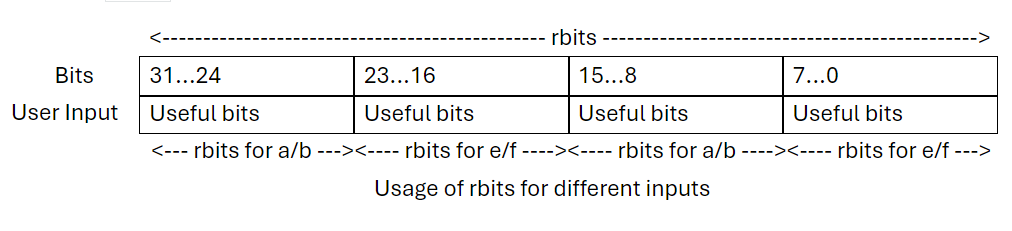
TransformerEngine generates a random seed and offset pair for each kernel that requires stochastic rounding (2 in the conventional recipe, one each for and ).
This is done in the host code prior to kernel launch:
  const size_t rng_elts_per_thread = 1024;  // Wild guess, probably can be tightened
  auto gen = at::get_generator_or_default<at::CUDAGeneratorImpl>(
      std::nullopt, at::cuda::detail::getDefaultCUDAGenerator());
  auto opts = at::TensorOptions().dtype(torch::kInt64).device(torch::kCUDA);

  at::PhiloxCudaState philox_args = init_philox_state(gen, rng_elts_per_thread);

  // 2 -> seed + offset
  auto rng_state = torch::empty({2}, opts);
  philox_unpack(philox_args, static_cast<int64_t*>(rng_state.data_ptr()));
  te_rng_state = makeTransformerEngineTensor(rng_state);
  quant_config.set_rng_state(te_rng_state.data());
The "wild guess" comment is verbatim from the TE code, as they are being overly conservative in the necessary "randomness" per thread.
Within the kernel, this seed / offset pair is then combined with a thread and tile specific index to generate random bits for each round of SR-quantization:
  const size_t rng_sequence
    = thread_idx + k_tile * 256 + linear_tile_idx * K_TILE_MAX * 256;

  transformer_engine::curanddx::detail::philox4x32_native_state<10> rng;
  rng.init(rng_seed, rng_sequence, rng_offset);
  uint4 random_uint4 = uint4{0, 0, 0, 0};
  ...
  random_uint4 = rng.generate4();
  ...
Each cvt.rs.satfinite.e2m1x4.f32 then consumes an uint32_t of these random bits per packed conversion.
Store from registers to global memory
After the entire 128 x 64 tile is quantized, the outputs are copied directly from rmem → gmem.
FP4E2M1 Store
  // Threadblock-level TiledCopy from `tmem` -> `rmem` and `rmem` -> `gmem`
  auto tiled_t2r = make_tmem_copy(TMEM_LOAD_NEW{}, bulk_tmem_epilogue(_,_,_,_0{}));
  auto tiled_r2g = make_tiled_copy_D(Copy_Atom<SM100_STORE_256bit_CACHE_NOALLOCATION, TC>{}, tiled_t2r);

  //Thread-level TiledCopy from `tmem` -> `rmem` and `rmem` -> `gmem`
  auto thr_t2r   = tiled_t2r.get_slice(thread_idx);
  auto thr_r2g = tiled_r2g.get_slice(thread_idx);

  // Tile-level view of `gmem` output tensor (128, 64)
  Tensor tCgC_mn = tCgC(_,_,_,tile_idx_m,tile_idx_n+k_tile);

  // Thread-level view of `gmem` output tensor (64)
  Tensor tDgC = thr_t2r.partition_D(tCgC_mn);

  // `rmem` fragments for storing quantization results
  Tensor tDrC = make_tensor<TC>(shape(tDgC));
  Tensor tDrC_frag = recast<cutlass::Array<TC, FragmentSize>>(coalesce(tDrC));

  // output_frgs now alias `tDrC_frag` pointer, which is a view of `tDrC` and hence `src`
  auto output_frgs = reinterpret_cast<cutlass::Array< TC, VectorSize> *>(tDrC_frag.data());
  // After quantization, `tDrC_frag` and in turn `tDrC` and `src` will contain the quantized `FP4E2M1` data
  ...

  // Re-tile `rmem` fragments to conform to layout of `rmem` -> `gmem` tiled copy
  // Here the `tDrC` and `tDgC` already match expected src / dst layouts
  Tensor src = thr_r2g.retile_S(tDrC);
  Tensor dst = thr_r2g.retile_D(tDgC);
  ...

  // Store quantized values
  copy(tiled_r2g, src, dst);
The above series of tensor manipulations boils down to extracting the thread-level ownership of the accumulators and indexing into the correct offset in the gmem tensor for storing the quantized values.
We can also check that tensor indexing works as expected.
For example, if we print out the tensors for thread 96:
tCgC:   subptr[4b](0x7f8046000000.0) o ((_128,_64),_1,_1,40,128):((8192,_1),_0,_0,1048576,_64)
tCgC_mn:        subptr[4b](0x7f8046e00c00.0) o ((_128,_64),_1,_1):((8192,_1),_0,_0)

src:    subptr[4b](0x7f8091fffc50.0) o ((_64,_1),_1,_1,_1):((_1,_0),_0,_0,_0)
dst:    subptr[4b](0x7f8046e60c00.0) o ((_64,_1),_1,_1,_1):((_1,_0),_0,_0,_0)
tCgCis the base pointer to thegmemoutput tensortCgC_mnis the offset for this output tiledstis the row that this thread is responsible for quantizing and storing to.
Recall that the input / output tensor is row-major 5120 x 8192, hence the 8192 row-stride.
If we find the byte difference between tCgC_mn and dst and convert it to elements, then divide by the row-stride, we should arrive at 96, since thread 96 is responsible for processing the 96'th row of the 128 x 64 tile.
offset in units of 4b elements= (0x7f8046e60c00-0x7f8046e00c00) * 8 // 4 = 786432offset in rows= 786432 // 8192 = 96
Finally, the CopyOp used to transfer from rmem → gmem is SM100_STORE_256bit_CACHE_NOALLOCATION. This is a wrapper around an sm100a-specific instruction st.global.L1::no_allocate.v8.f32, which copies 8 floats (= 64 FP4s) from rmem → gmem while hinting to the compiler to skip L1 cache.
FP8E4M3 Scale Factor Store
  // Same as above
  auto tiled_t2r = make_tmem_copy(TMEM_LOAD_NEW{}, bulk_tmem_epilogue(_,_,_,_0{}));
  auto thr_t2r   = tiled_t2r.get_slice(thread_idx);

  // Tile-level view of scale factor output tensor
  Tensor tCgSFC_mn = gSFC_mn(_,_,tile_idx_m,tile_idx_n+k_tile);

  // Create "dummy" dimensions to match the rank expected by thr_t2r
  Tensor tCgSFC = make_tensor(tCgSFC_mn.data(), make_layout(
                              make_shape(shape(tCgSFC_mn), Int<1>{}, Int<1>{}),
                              make_stride(stride(tCgSFC_mn), Int<0>{}, Int<0>{})
                              ));
  // Partition tile-level tensor to get thread-level view and remove extraneous dimensions
  Tensor tDgSFC = filter(thr_t2r.partition_D(tCgSFC));

  // Create `rmem` tensor for storing scale factor computation results
  Tensor tDrSFC = make_tensor<TSFC>(shape(tDgSFC));
  // tC_rRowSFD_frg aliases tensor tDrSFC
  Tensor tC_rRowSFD_frg = recast<cutlass::Array<TSFC, NumVecs>>(tDrSFC);

  // Compute scale factors
  auto pvscales_cvted = cutlass::NumericArrayConverter<TSFC, ElementAccumulator, NumVecs>{}(pvscales);
  // Copy converted scales to tC_rRowSFD_frg which alias tDrSFC
  tC_rRowSFD_frg(_0{}) = pvscales_cvted;
  ...
  // Store blockwise decode scales
  copy(AutoVectorizingCopyWithAssumedAlignment<128>{}, tDrSFC, tDgSFC);
Storing the decode scale factors from rmem → gmem is similar to storing the FP4E2M1 quantized values. The primary difference is the CopyAtom used.
Here the copy atom is AutoVectorizingCopyWithAssumedAlignment<128>, which attempts to vectorize the copy up to 128 bits. Since we're storing 4 scale factors, each 8 bits, the copy casts the 4 FP8E4M3 elements to a single uint32_t and issues a single st.global.
Fini
That wraps up the systems engineering that TransformerEngine employs to make NVFP4 training recipe perform at scale.
These optimizations combined with the stabilization mechanisms we covered in Part 1 are what make NVFP4 training feasible.
Stay tuned for the upcoming blogs where we will analyze the training dynamics of novel hybrid architectures under NVFP4!
Previous: Part 1: NVFP4 Recipe
References
Cook et al. "Four Over Six: More Accurate NVFP4 Quantization with Adaptive Block Scaling." arXiv (2025).
Castro et al. "Quartet: Native FP4 Training Can Be Optimal for Large Language Models." arXiv (2025).
NVIDIA. "Pretraining Large Language Models with NVFP4." arXiv (2025).
NVIDIA. "Nemotron 3: Efficient and Open Intelligence." arXiv (2025).